

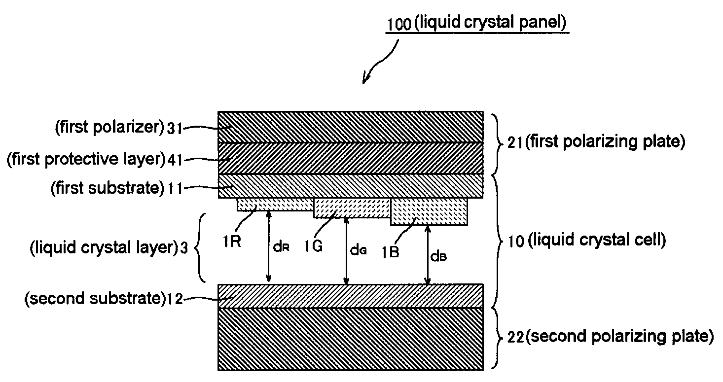
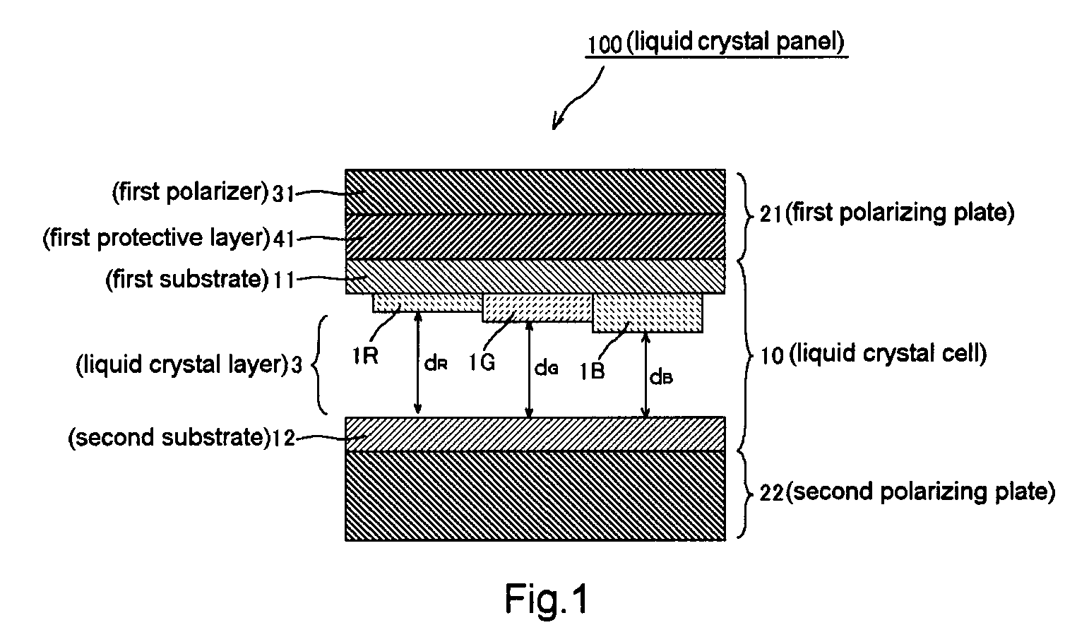
Liquid crystal panel provided with liquid crystal cell having multigap structure, and liquid crystal display
a liquid crystal panel and multi-gap technology, applied in the field of liquid crystal panels, can solve the problem of large color shift in oblique directions
- Summary
- Abstract
- Description
- Claims
- Application Information
AI Technical Summary
Benefits of technology
Problems solved by technology
Method used
Image

Examples
reference example 1
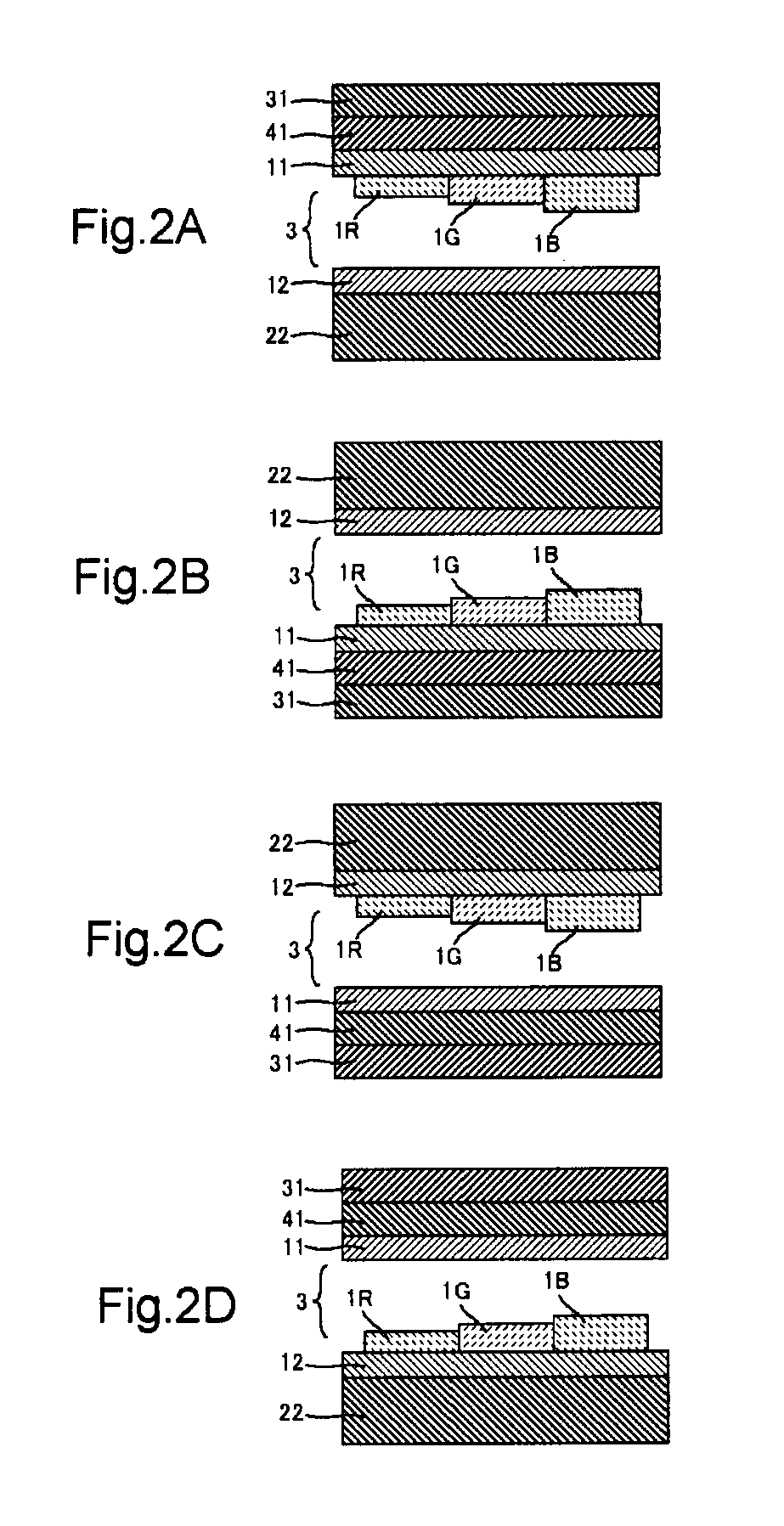
Formation of Liquid Crystal Cell
[0106]A colored resin solution wherein a pigment was dispersed was coated onto a glass substrate on which a black matrix was formed, and the resultant was pre-baked so as to be dried, and a colored resin layer was formed. Next, a positive resist was coated onto the colored resin layer, and the resultant was exposed to light, by using a photomask. A developing solution was used to develop the positive resist, and the colored resin layer was etched. Thereafter, the positive resist was peeled off. In order to form red, green and blue filters, this operation was repeated three times to form a color filter substrate while the thicknesses of the colored resin layers in the individual colors (color filters) were made different from each other.
[0107]Next, thin film transistors, scanning lines, signal lines, and pixel electrodes were formed on another glass substrate to form an active matrix substrate. Alignment films were formed on the two substrates, respect...
reference example 2
Formation of First Polarizing Plate
[0110]A polymeric film [trade name: “VF-PS#7500”, manufactured by Kuraray Co., Ltd.], 75 μm in thickness, made mainly of a polyvinyl-alcohol-based resin was immersed in an aqueous solution containing iodine and potassium iodide (iodine concentration=0.03% by weight) while a tensile force was applied thereto in the longitudinal direction of the film. The film was drawn to make the final drawn length 6.2 times longer than the original length, and thereby forming a polarizer (a). This polarizer (a) had the following properties: thickness=25 μm, polarization degree P=99%, and single transmittance T=43.5%
[0111]Next, a tenter drawing machine was used to draw a polymeric film [trade name: “ZEONOR ZF14”, manufactured by Optes Inc.], 40 μm in thickness, containing a norbornene-based resin 1.2 times in an air-circulating constant-temperature oven of 150° C. by fixed-end transverse uniaxial drawing, and thereby forming a retardation film (a). In this retardat...
reference example 3
Formation of Second Polarizing Plate
[0120]A commercially available polarizing plate [NPF-TEG1224DU, manufactured by Nitto Denko Corp.] was used as a polarizing plate (b). In this polarizing plate (b), its polarizer had, on both sides thereof, a triacetylcellulose film (thickness: 40 μm) as a protective layer. In this triacetylcellulose film, the index ellipsoid thereof satisfied the relationship of nx=ny>nz, and the Rth[550] was 40 nm.
PUM
 Abstract
Description
Claims
Application Information