
Symmetrical cooperative diversity in the relay-enabled wireless systems

a wireless system and cooperative technology, applied in the field of symmetrical cooperative diversity in the relay-enabled wireless system, can solve the problems of affecting communication, affecting communication, and affecting the quality of communication,

Inactive Publication Date: 2009-08-20
WSOU INVESTMENTS LLC +1
View PDF10 Cites 21 Cited by
  • Summary
  • Abstract
  • Description
  • Claims
  • Application Information

AI Technical Summary

Benefits of technology

The present patent application provides a communication system that includes a source, a destination, and multiple relays. The relays receive a first broadcast including a first source transmission and a first relay transmission, which includes a prior source transmission. The destination node receives the first broadcast and a second broadcast, which includes a second source transmission and a second relay transmission. The second relay transmission includes the first source transmission and the second relay transmission. The system uses a linear minimum mean square error decision feedback equalizer receiver to detect transmitted data symbols. The technical effect of this invention is to improve the reliability and stability of wireless network communication by rebroadcasting transmissions between the source and destination nodes using multiple relays.

Problems solved by technology

However, this configuration, as described in greater detail below, also suffers from limitations.
These limitations in distance are caused by multiple factors.
Furthermore, wireless communications typically require substantially line-of-site access between a transmitter and receiver, such that an intermediate structure may block or otherwise attenuate the transmission sufficiently to degrade communications.
However, as described in greater detail below, the conventional relay configuration result in sub-optimal performance due to factors, such as non-uniform signal amplification.

Method used


Image

  • Symmetrical cooperative diversity in the relay-enabled wireless systems
  • Symmetrical cooperative diversity in the relay-enabled wireless systems
  • Symmetrical cooperative diversity in the relay-enabled wireless systems

Examples


Embodiment Construction

)

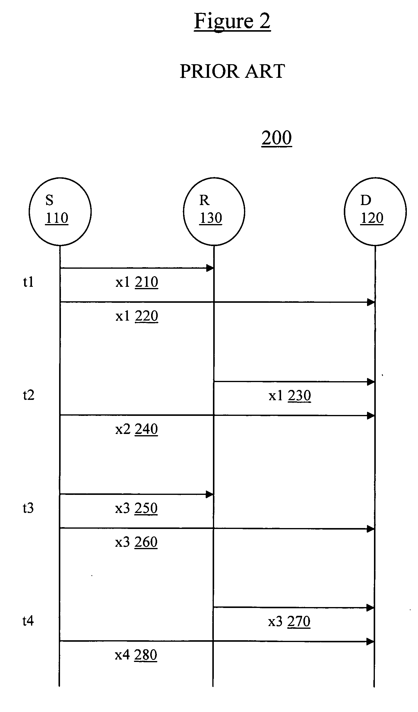
[0031]In cooperative relaying, a relay R processes received signals from a source S and to retransmit to a destination D by means of AF (amplify-and-forward) or DF (detection-and-forward) modes. Typically, the relay R receives a transmission from the source in a first time cycle, and then rebroadcasts the received transmission in a second, subsequent time cycle.

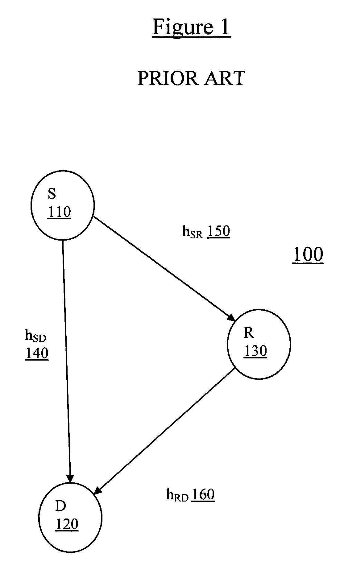
[0032]Cooperative diversity is conventional cooperative relaying strategy to provide diversity gain to the system without increasing transmission time or transmission bandwidth. Referring now to FIG. 1 (Prior Art), a cooperative diversity system 100 has a source S 110, a destination D120, and a single relay R 130 with single antenna transmitter and receiver (or transceiver). As depicted in FIG. 1, an information source S 110 and a destination D 120 communicate to each other either directly from S 110 to D 120 via a transmission hSD 140 or through an indirect relay station R 130 to the destination D 120 via transmissions hSR ...


PUM


Abstract

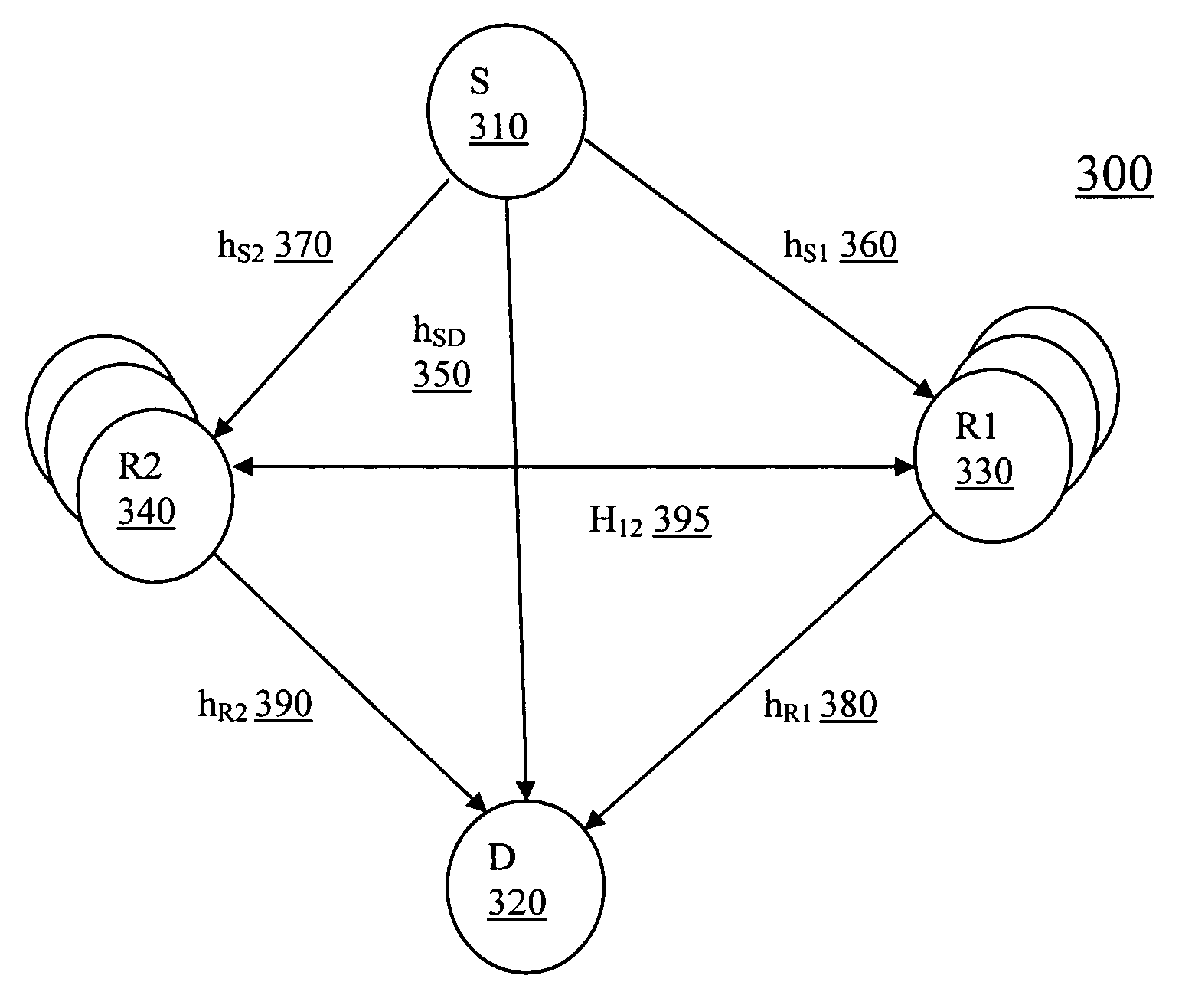
A communications system includes a source, a destination, and multiple relays. In a first time period, the source emits a first transmission and a first relay retransmits a prior source transmission. Then, in a second, subsequent time period, the source node emits a second transmission and a second relay transmits the source transmission from the first time period. Optionally, the transmission from the second relay also includes the message from the first relay during the first time period. Similarly, in a third time period, the first relay transmits a message that includes the second relay's transmission and the second source transmission from the second time period. Alternatively, the source node transmit in a first frequency band, the first and second relays receive only in the first frequency band, and retransmit in a second frequency band, and the destination receives in both the first and second frequency bands.

Description

BACKGROUND OF THE INVENTION[0001]1. Field of the Invention[0002]The present application generally relates to a system and method for providing a wireless system having multiple relays with coordinated operation.[0003]2. Description of the Related Art[0004]A Wireless Distribution System (WDS) is a system that enables the wireless interconnection of access points (AP) in an IEEE 802.11 network. The WDS allows a wireless network to be expanded using multiple access points without the need for a wired backbone to link them, as is conventionally required. The notable advantage of WDS over other solutions is that it preserves the MAC addresses of client packets across links between access points. An access point can be either a main, relay or remote base station. A main base station is typically connected to the wired Ethernet. A relay base station relays data between remote base stations, wireless clients or other relay stations to either a main or another relay base station. A remote ba...

Claims


Application Information

Patent Timeline
Patent Type & Authority Applications(United States)
IPC IPC(8): H04B7/14H04B7/02
CPCH04B7/02H04B7/026H04B7/15592H04W88/04H04W48/20H04W72/005H04B7/18523H04W72/30
Inventor REID, TONYGREEN, MARILYNN
Owner WSOU INVESTMENTS LLC
Learn More