Delay-Based Modulation of RF Communications Signals

a delay-based, signal-based technology, applied in the field of delay-based modulation of signals, can solve the problems of limited effective tuning capability of vco, inability to continue to oscillate unabated, and inability to achieve linear operation of vco,

Inactive Publication Date: 2009-08-20
PANASONIC CORP
View PDF7 Cites 13 Cited by
  • Summary
  • Abstract
  • Description
  • Claims
  • Application Information

AI Technical Summary

Benefits of technology

[0019]The delay-based modulation methods and apparatus of the present invention may be advantageously employed in RF transmitters and receivers. According to one embodiment of the invention, an RF oscillatory signal generated by a tunable oscillator apparatus serves as an RF carrier signal in a polar transmitter apparatus and the angle control signal used to control the delay of a variable time delay circuit comprises a phase modulation signal from the phase path of the polar transmitter. Because the phase modulation is applied to the carrier signal using the variable time...

Problems solved by technology

However, because the capacitors and inductors of the tank circuit 102 are not ideal (they each include some finite amount of resistance), the oscillator 100 cannot continue to oscillate unabated absent some mechanism to counteract the non-idealities.
However, in wideband applications the effective tuning capability of the VCO is limited by the capacitance versus voltage (CV) characteristics of its varactor diodes.
This variation in Kv leads to nonlinear operation of the VCO, which is a highly undesirable condition since the nonlinearities cause PM-PM d...

Method used


Image

  • Delay-Based Modulation of RF Communications Signals
  • Delay-Based Modulation of RF Communications Signals
  • Delay-Based Modulation of RF Communications Signals

Examples


Embodiment Construction

[0030]Those of ordinary skill in the art will realize that the following detailed description of the present invention is illustrative only and is not intended to be in any way limiting. Other embodiments of the present invention will readily suggest themselves to such skilled persons having the benefit of this disclosure. Reference will now be made in detail to implementations of the present invention as illustrated in the accompanying drawings. The same reference indicators will be used throughout the drawings and the following detailed description to refer to the same or like parts.

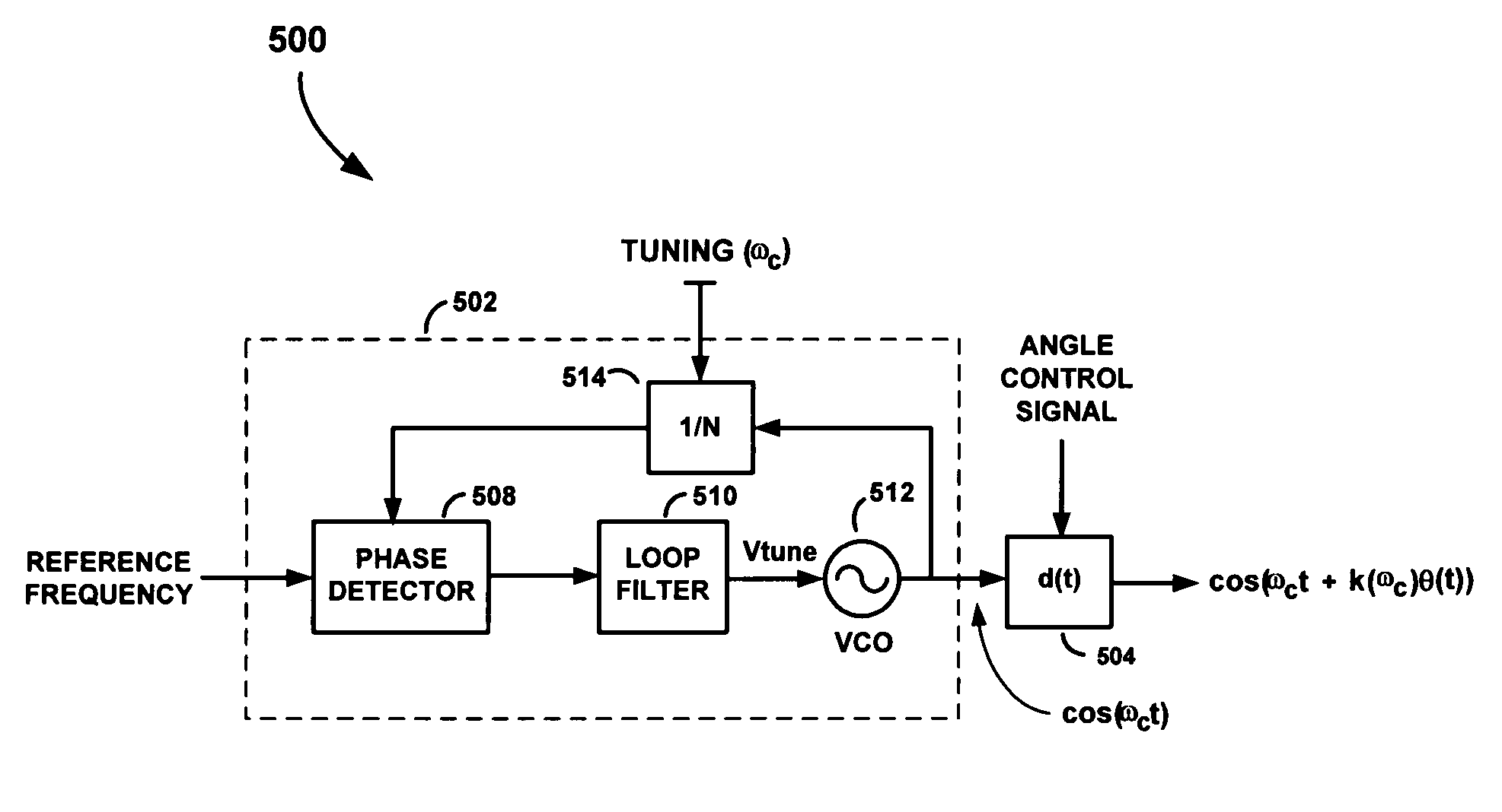
[0031]Referring first to FIG. 5, there is shown a block diagram of an angle modulator apparatus 500, according to an embodiment of the present invention. The angle modulator apparatus 500 comprises a phase-locked loop (PLL) 502 and a variable time delay circuit 504. The PLL 502 includes a phase detector 508, a loop filter 510, a VCO 512 and a feedback loop containing a frequency divider 514. The variab...


PUM


Abstract

An apparatus for providing an angle modulated signal includes a tunable oscillator circuit, a variable time delay circuit, and an optional scaling and delay control apparatus. The tunable oscillator circuit generates an oscillatory signal having a predetermined frequency. The variable time delay circuit operates to delay the oscillatory signal in accordance with time varying changes in an angle control signal, thereby producing the desired angle modulated signal. The scaling and delay control apparatus is configured to scale the angle control signal to account for frequency dependent phase delays of the oscillatory signal through the variable time delay circuit. The methods and apparatus of the present invention may be advantageously used in RF transmitters and receivers, such as in a polar transmitter, where the oscillatory signal generated by the tunable oscillator apparatus serves as a carrier signal, and the angle control signal used to control the delay of the variable time delay circuit comprises a phase modulation signal from the phase path of the polar transmitter.

Description

FIELD OF THE INVENTION[0001]The present invention relates to modulation of signals. More particularly, the present invention relates to delay-based modulation of signals.BACKGROUND OF THE INVENTION[0002]A voltage controlled oscillator (VCO) is an electrical oscillator that generates an oscillatory signal having a frequency which is dependent on a control voltage. VCOs provide important functions in communication systems and other electronic systems. They are used in both analog and digital systems, and are essential components in virtually every radio frequency (RF) communication system.[0003]FIG. 1 is a schematic drawing of a commonly used VCO 100, as is known in the art. The VCO 100 comprises an inductive-capacitive (L-C) tank circuit 102, first and second cross-coupled transistors 112 and 114, and a current source 116. The tank circuit 102 includes first and second inductors 104 and 106 and first and second varactor diodes 108 and 110. As will be explained in more detail below, t...

Claims


Application Information

Patent Timeline
IPC IPC(8): H03C3/00H03K7/06H04L27/12
CPCH03C3/00H04L27/12H03K7/06
Inventor OSMAN, SALEHMCCUNE, JR., EARL W.
Owner PANASONIC CORP
Why Eureka
Try Eureka