
Transmitter identification information signal detection apparatus and method

a technology of identification information and detection apparatus, which is applied in the field of circuits and methods for detecting tii signals in digital audio broadcasts, can solve the problems of prior art not meeting the requirements of real-time network, and the time-consuming process of checking every sub-carrier of null symbols

Active Publication Date: 2009-08-20
VIA TECH INC
View PDF7 Cites 3 Cited by
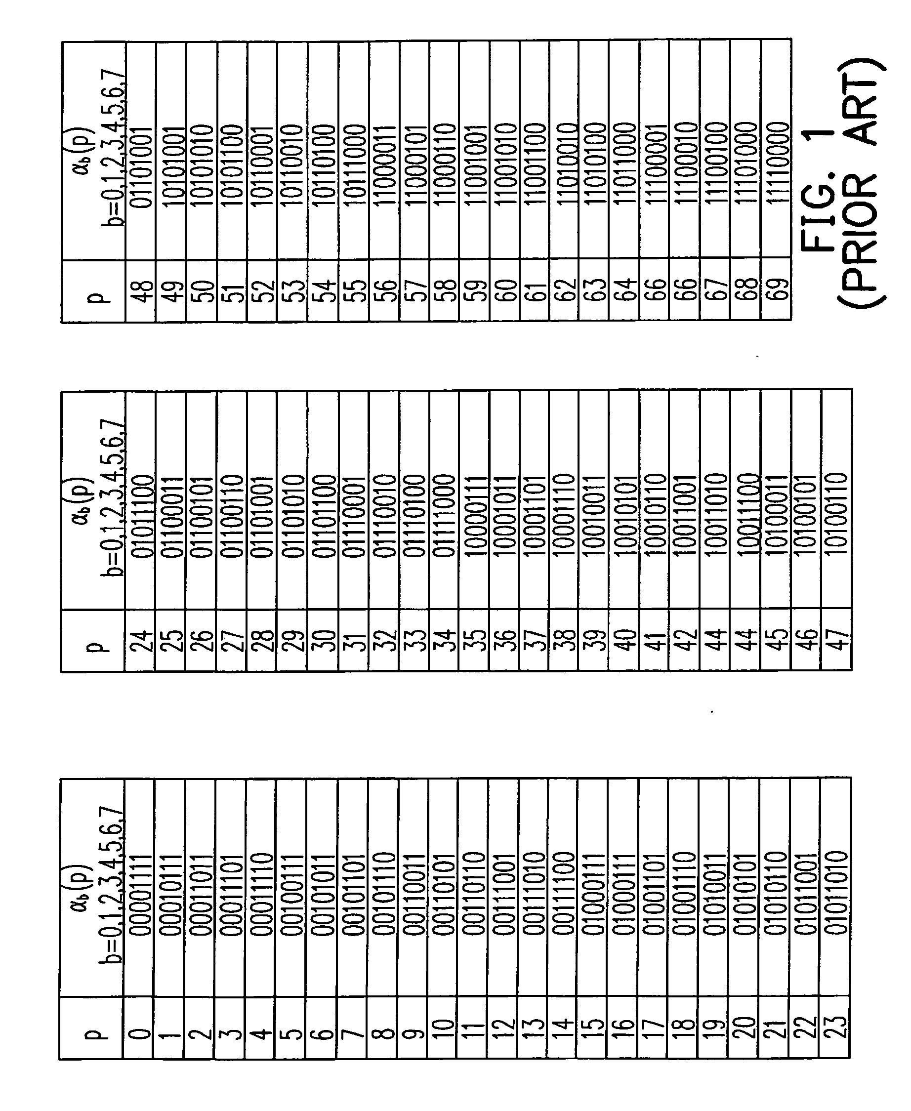
  • Summary
  • Abstract
  • Description
  • Claims
  • Application Information

AI Technical Summary

Benefits of technology

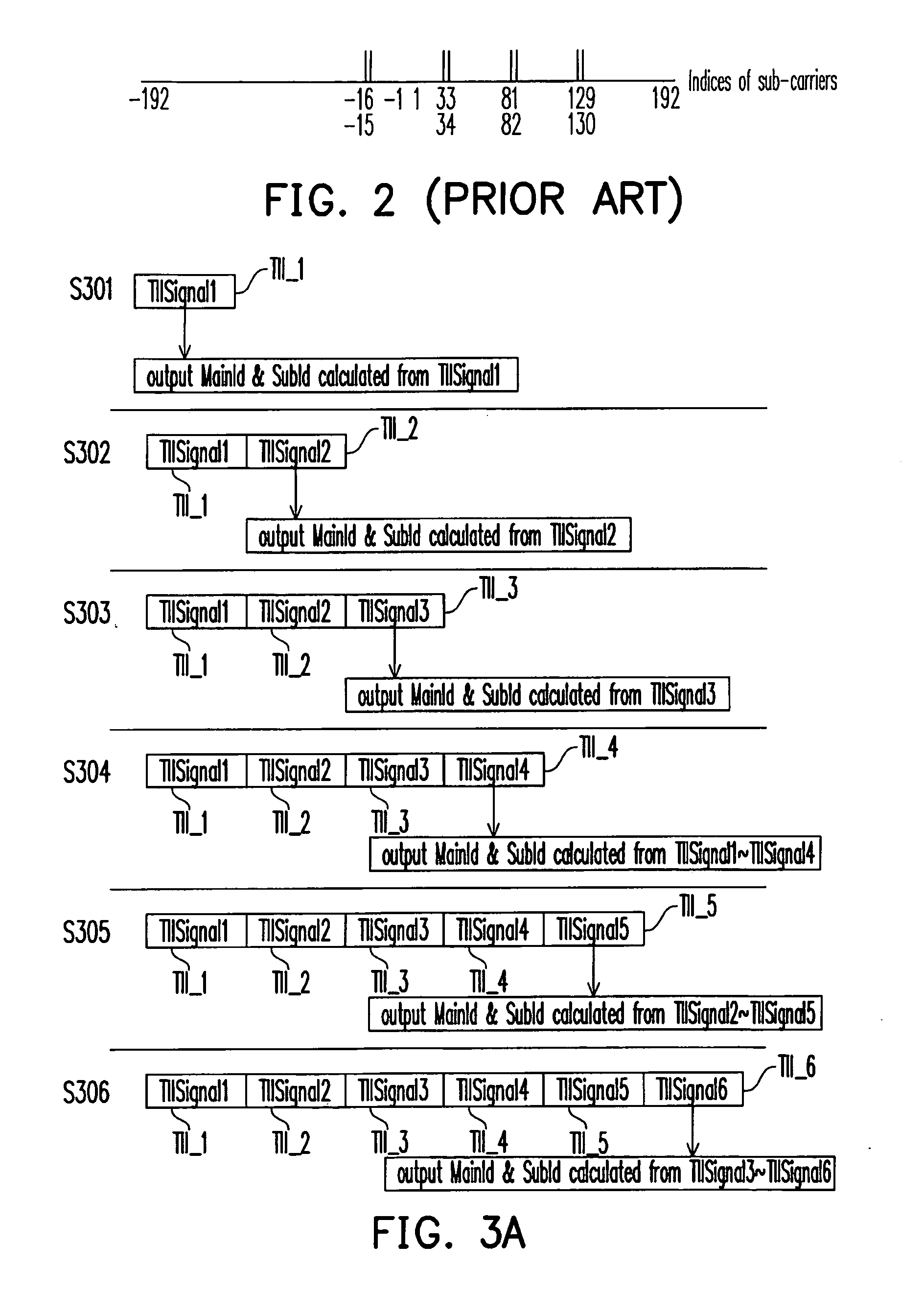
[0019]In summary, the TII signal detection circuit, the method and the receiver provided by the present invention function to conduct cross-correlation calculation once for every two adjacent sub-carrier signals and groups division, thus, the memory or the register required for the function can be reduced. Moreover, thanks to the mechanism of correcting MainId and SubId, the probability of correctly decoding the TII signal is close to 100%. Compared to the conventional circuit and method, the advantage of the present invention rests in simplicity of implementation, less calculation time and high robustness against noise and interference.
rests in simplicity of implementation, less calculation time and high robustness against noise and interference.

Problems solved by technology

Furthermore, the procedure to check every sub-carrier of the null symbols consumes a great amount of time.
In short, the conventional TII signal detection method takes too long time and needs a register with large capacity to register sub-carrier signals, therefore, the prior art does not meet the requirement of real-time network.

Method used


Image

  • Transmitter identification information signal detection apparatus and method
  • Transmitter identification information signal detection apparatus and method
  • Transmitter identification information signal detection apparatus and method

Examples


Embodiment Construction

[0031]Reference will now be made in detail to the present preferred embodiments of the invention, examples of which are illustrated in the accompanying drawings. Wherever possible, the same reference numbers are used in the drawings and the description to refer to the same or like parts.

[0032]The embodiment of the present invention provides a circuit and a method for detecting TII in an OFDM system. Compared to the prior art, the present invention is advantageous in simplicity of implementation, less calculation time and high robustness against noise and interference.

[0033]The present invention is exemplary for a DAB system application, but the disclosed embodiment of the present invention is not limited to be applied to the DAB system. In the embodiment, the major idea is to use the cross-correlation between a PRS and a TII signal defined in the DAB standard to detect the TII signal, and thereby to solve the coding value p of MainId and the coding value c of SubId. Since the TII si...


PUM


Abstract

A transmitter identification information (TII) signal detection circuit is suitable for an orthogonal frequency division modulation system. A TII signal detection circuit receives a TII signal and conducts a cross-correlation calculation on the TII signal and a phase reference symbol (PRS) so as to obtain a present cross-correlation result, and then, sums the cross-correlation results obtained by conducting cross-correlations on AVE_TF_NUM-1 pieces of TII signals and the PRS and the present cross-correlation result so as to obtain an accumulated cross-correlation result. After that, a plurality of indices corresponding to a plurality of maximal values in the accumulated cross-correlation result is found out according to the accumulated cross-correlation result. Finally, a present main identifier (MainId) and a present sub-identifier (SubId) are calculated according to the four indices corresponding to the four maximal values, wherein the cross-correlation calculation is conducted on the TII signal and the PRS of every two adjacent sub-carriers.

Description

CROSS-REFERENCE TO RELATED APPLICATION[0001]This application claims the priority benefit of China application serial no. 200810081258.3, filed on Feb. 20, 2008. The entirety of the above-mentioned patent application is hereby incorporated by reference herein and made a part of this specification.BACKGROUND OF THE INVENTION[0002]1. Field of the Invention[0003]The present invention generally relates to a digital transmitter identification information signal (TII signal) detection circuit and the method thereof, and more particularly, to a circuit and a method for detecting TII signal in a digital audio broadcast (DAB) system.[0004]2. Description of Related Art[0005]A DAB system is a broadcast system with high transmission quality, where the system adopts OFDM (Orthogonal Frequency Division Modulation) scheme so as to possess good robustness against channel decay and noise.[0006]In the DAB standard, a TII signal is carried by an OFDM symbol, and the TII signal is defined at a position ...

Claims


Application Information

Patent Timeline
IPC IPC(8): H04L27/06
CPCH04H60/50H04L27/2647H04H2201/20
Inventor YAN, LIANGZHAO, GUANGLING
Owner VIA TECH INC
Learn More