Tube unit, control unit, and micropump

a control unit and tube technology, applied in the direction of positive displacement liquid engine, pipe, pump, etc., can solve the problems of affecting the discharge performance, the inability to obtain the discharge accuracy, and the inability to obtain the desired drive performan

Inactive Publication Date: 2009-08-20
SEIKO EPSON CORP
View PDF3 Cites 44 Cited by
  • Summary
  • Abstract
  • Description
  • Claims
  • Application Information

AI Technical Summary

Benefits of technology

[0046]According to this kind of configuration, as the control unit includes the motor, it not being necessary to bring the motor and the drive force transmission mechanism out of engagement, it is possible to make a drive system formed of the motor and the drive force transmission mechanism a configuration having a stable engagement condition.

Problems solved by technology

However, it being difficult for a user to mount a soft and thin tube alone on a pump main body, it is conceivable that it affects a discharge performance.
Also, generally, a diameter of the tube varies widely, and this variation causes a variation in a tube pressing magnitude, leading to an impossibility of obtaining the discharge accuracy, as well as an overload on a small motor acting as a drive source, meaning that it is also conceivable that it is impossible to obtain a desired drive performance and, at worst, it is impossible to drive the apparatus.

Method used


Image

  • Tube unit, control unit, and micropump
  • Tube unit, control unit, and micropump
  • Tube unit, control unit, and micropump

Examples


embodiment 1

Another Example of Embodiment 1

[0121]As a structure of regulating the position of the fingers 40 to 46 in the forward-back direction, it is possible to employ a structure in which a flange like protrusion acting as a stopper is provided partway along the shaft of each finger.

[0122]FIG. 5 is a fragmentary sectional view showing a micropump according to another example of the embodiment 1. A description will be given with the finger 44 as an example. In FIG. 5, the finger 44 has a stopper 44e, as the flange like protrusion, formed partway along a shaft 44a in an axial direction. The one end of the shaft 44a, being the cam abutment portion 44b, has the same shape as in the heretofore described embodiment 1 (refer to FIGS. 2 and 4), while the other end is the tube pressing portion 44d.

[0123]Also, a stopper groove 30 is formed in the guide frame 14 (first guide frame 15 and second guide frame 16), and the stopper 44e of the finger 44 is housed therein. A forward and back position of the...

embodiment 2

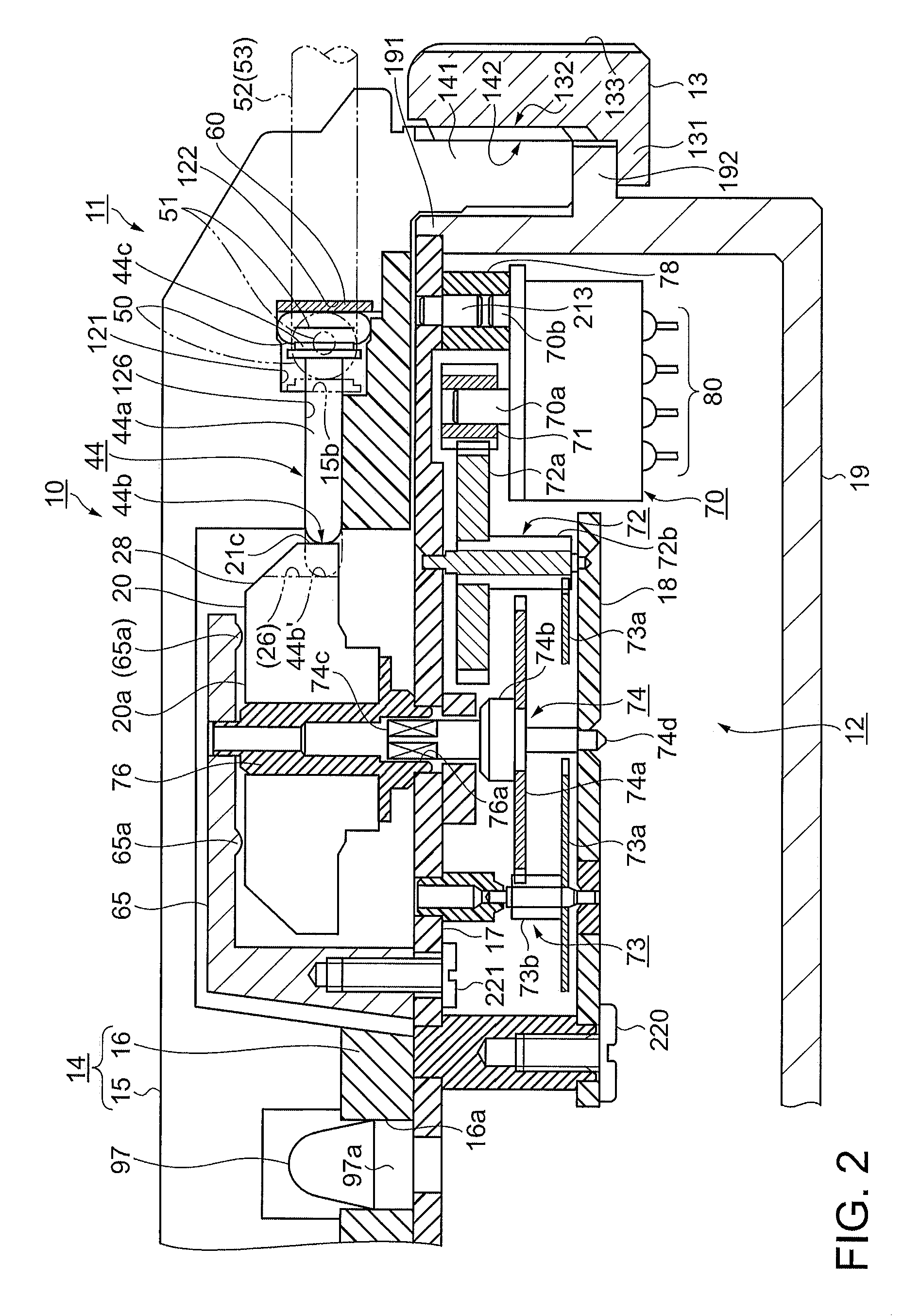
[0126]Continuing, a description will be given of the micropump according to an embodiment 2, referring to the drawings. The embodiment 2 has a feature wherein a motor which drives a cam is provided in a tube unit. Consequently, an illustration and description will be given centered on differing points. The same functional components and regions as those of the embodiment 1 are indicated by the same reference numbers and characters.

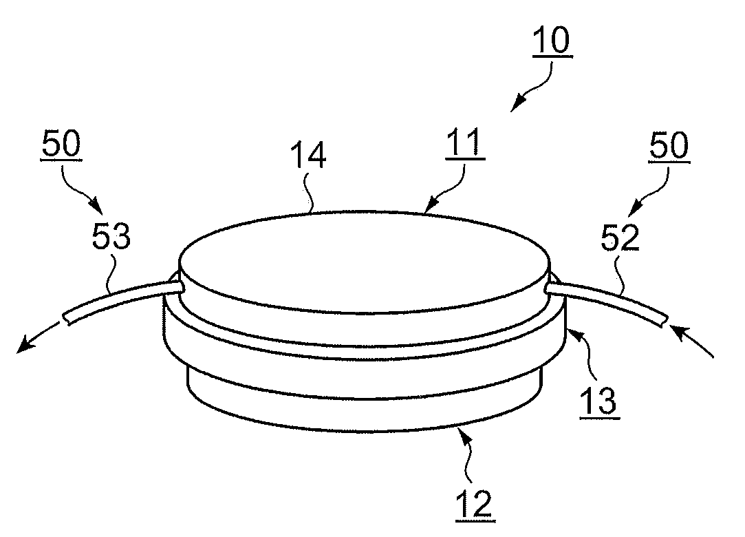
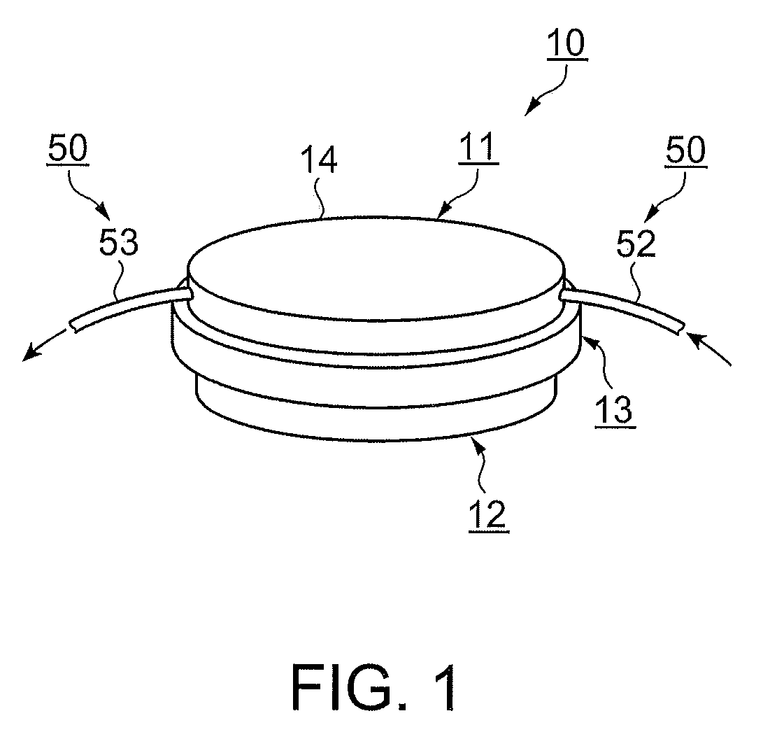
[0127]FIG. 6 is a fragmentary sectional view showing the micropump according to the embodiment 2. FIG. 6 shows a condition in which the tube unit 11 and the control unit 12 are connected, and ready to be driven. In FIG. 6, the motor 70 is attached to the tube unit 11. Consequently, the tube 50 and the plurality of fingers, and the motor 70 are formed into the tube unit 11 while being held by the guide frame 14. On the other hand, the control unit 12 is configured of the cam 20, the drive force transmission mechanism, and the control circuitry.

[0128]The mot...


PUM


Abstract

A micropump includes: a tube unit including a tube which has elasticity, and one portion of which is disposed in an arc shape, a plurality of fingers, which are disposed radiating from a direction of a center of the arc shape of the tube, and a guide frame, which holds the tube and the plurality of fingers; and a control unit including a cam, which sequentially presses the plurality of fingers in a direction in which a liquid flows, a drive force transmission mechanism, which transmits a torque to the cam, and a control circuitry, which carries out a control of a motor which drives the drive force transmission mechanism, wherein the tube unit and the control unit are attached stacked one on the other, and are detachable.

Description

CROSS REFERENCE TO RELATED ART[0001]The disclosure of Japanese Patent Applications No. 2008-032797 filed on Feb. 14, 2008 and No. 2008-279325 filed on Oct. 30, 2008 including specification, drawings and claims is incorporated herein by reference in its entirety.BACKGROUND[0002]1. Technical Field[0003]The present invention relates to a tube unit, a control unit, and a micropump configured by the units being connected in such a way as to be attachable and detachable.[0004]2. Related Art[0005]To date, a small peristaltic pump apparatus has been known in which a pump module, which includes a tube and a rotor which presses the tube, and a motor module, which has a step motor and an output gear mechanism, are assembled stacked one on the other, a gear acting as a connecting element is provided on a rotary shaft of the rotor, and a pinion acting as a power takeoff mechanism is provided on the output gear mechanism, wherein, on the pump module and the motor module being connected stacked on...

Claims


Application Information

Patent Timeline
Patent Type & Authority Applications(United States)
IPC IPC(8): F04B17/00F16L9/00
CPCA61M5/14228F04B43/123F04B43/12
Inventor MIYAZAKI, HAJIMEMIYASAKA, MAMORUKAWASUMI, KAZUO
Owner SEIKO EPSON CORP
Why Eureka
Try Eureka