
Electric device assembly and film-covered electric device structure

a technology of electric devices and assembly parts, applied in the direction of cell components, electrochemical generators, flat cell groupings, etc., can solve the problems of difficult to uniformly cool the two battery cells, difficult to enlarge the assembled battery, and difficult for an elastic material with high hardness to absorb relatively weak vibrations

Active Publication Date: 2009-08-20
NEC CORP
View PDF10 Cites 82 Cited by
  • Summary
  • Abstract
  • Description
  • Claims
  • Application Information

AI Technical Summary

Benefits of technology

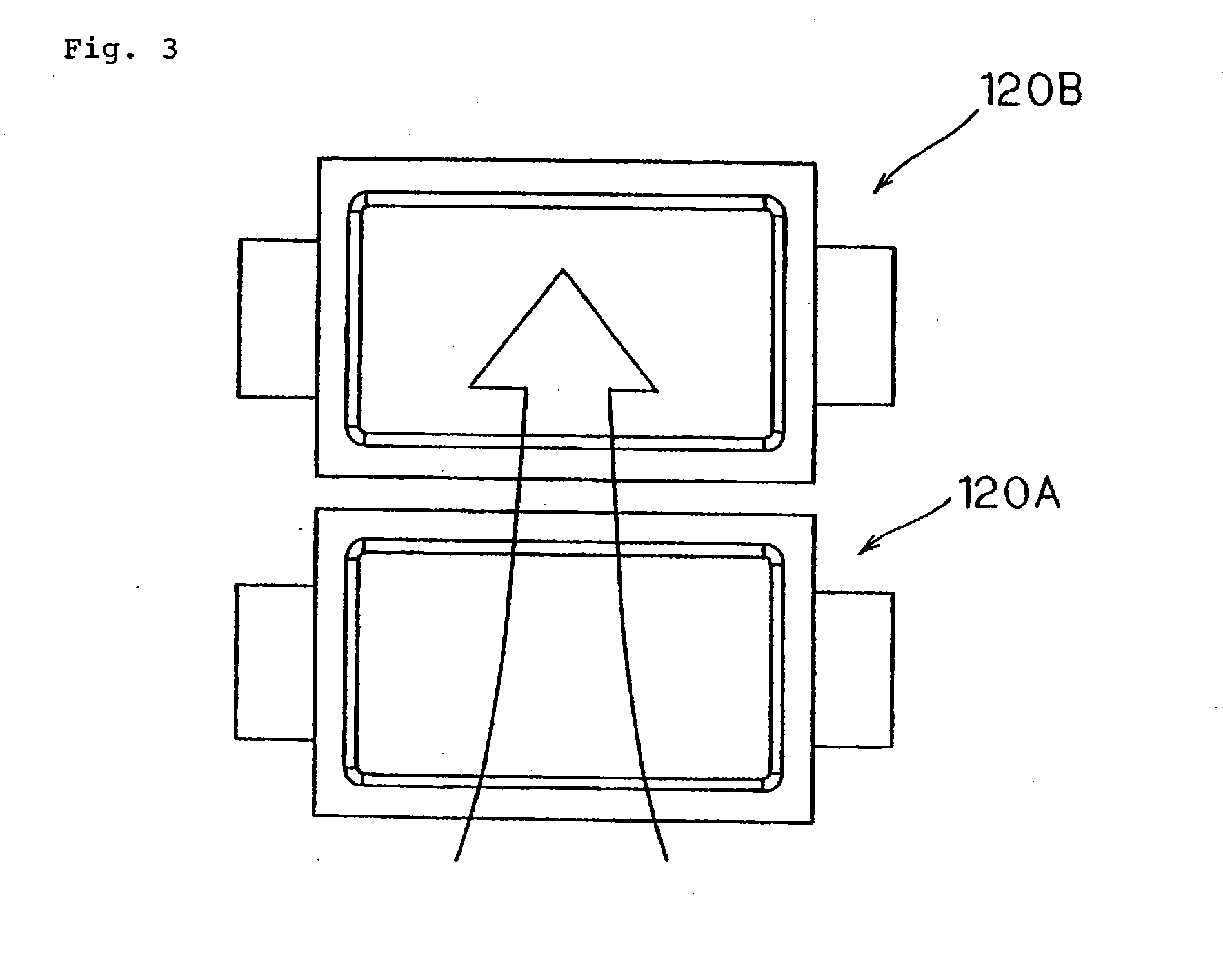
[0010]In configuring an assembled battery, there is also an arrangement in which battery cells 120A and 120B are two-dimensionally provided as shown in FIG. 3. In this configuration, however it is impossible to uniformly cool the two battery cells even if air is blown from the side of one battery cell (at bottom the side in the drawing) to the other side of the battery cell (at the top side in the drawing) as illustrated with an arrow, for example. This is because cooling air is warmed as it passes through first battery cell 120A so that this warmed air is supplied to second battery cell 120B, thus producing a difference in cooling between the two battery cells.

Problems solved by technology

In this configuration, however it is impossible to uniformly cool the two battery cells even if air is blown from the side of one battery cell (at bottom the side in the drawing) to the other side of the battery cell (at the top side in the drawing) as illustrated with an arrow, for example.
However, provision of such a duct will enlarge the assembled battery.
However, it is difficult for an elastic material with high hardness to absorb relatively weak vibrations etc, hence a separate mechanism for absorbing relatively weak force is needed.

Method used


Image

  • Electric device assembly and film-covered electric device structure
  • Electric device assembly and film-covered electric device structure
  • Electric device assembly and film-covered electric device structure

Examples


Embodiment Construction

[0052]Referring next to the drawings, the exemplary embodiment of an electric device assembly of the present invention will be described taking an example of an assembled battery including a group of film-covered batteries. FIG. 4 is an external perspective view showing an assembled battery of the exemplary embodiment. FIG. 5 is a perspective view showing a battery cell unit used in an assembled battery of the exemplary embodiment.

[0053]As shown in FIG. 4, assembled battery 80 is comprised of six parallel-arranged modules 50 provided in layers, each having two battery cells 20A and 20B (also called “battery cells 20”). Pressure contact members 60 are laid out on both sides (with respect to the X-direction in the drawing) of parallel-arranged modules 50.

[0054]A conventional typical film-covered battery shown in FIG. 5 can be used as battery cell 20. Battery cell 20 is a lithium ion secondary battery, and accommodates battery element 22 with an electrolyte inside a closed space formed...


PUM


Abstract

Assembled battery (80) includes two battery cells (20A, 20B) arranged in parallel, which are accommodated in single parallel-arranged module (50). Inter-battery airflow passage (65) is formed between parallel-arranged modules so as to allow cooling air to pass therethrough. Pressure contact members (60) each have hollow portion (61) formed by solid portion (66) and thin wall portion (61a) and are arranged in layers. Hollow portion (61) forms a cooling air passage. Cooling air supplied to the cooling air passage is sent to battery cell (20B) on the rear side, and directed and supplied toward the central part of battery cell (20B). Solid portions (66) in area A hold electrode tab (25) therebetween while pressure contact members (60) are in contact with each other in area B.

Description

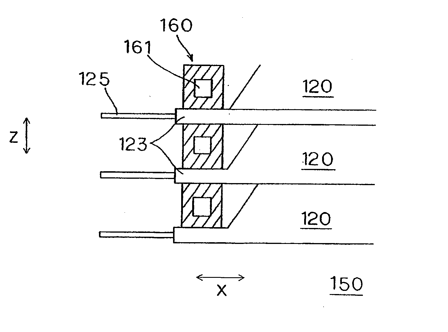
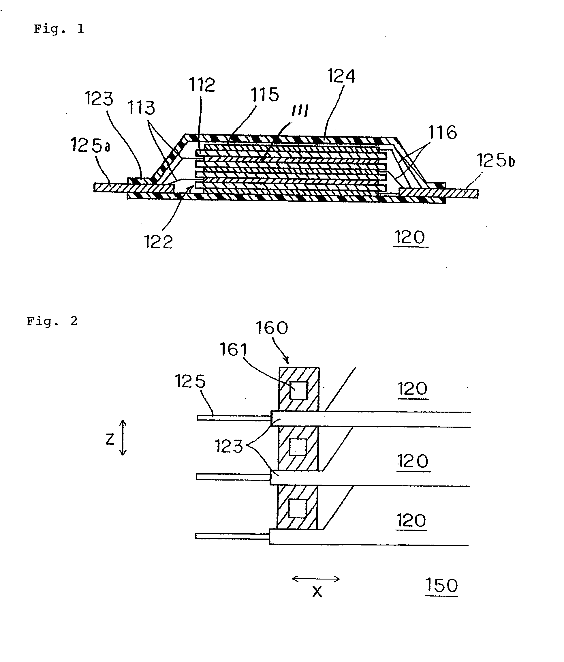
TECHNICAL FIELD[0001]The present invention relates to an electric device assembly made up of a plurality of film-covered electric devices (e.g. film-covered batteries).BACKGROUND TECHNOLOGY[0002]In recent years, as an electric power source for driving electric vehicles etc., use of an assembled battery made of a plurality of lithium ion secondary cells that are covered by film for instance have been made. It has been known that, with such an assembled battery, in order to maximize the charging and discharging performance of the battery (or in order to avoid reduction of battery life), each of the film-covered cells need to be cooled.[0003]FIG. 1 shows a configuration of a conventional typical battery cell (film-covered battery). Battery cell 120 includes battery element 122 arranged inside a closed space formed by packaging film 124. Battery element 122 is comprised of alternately layered positive and negative electrode plates 111 and 115 separated by separators 112 and an electroly...

Claims


Application Information

Patent Timeline
IPC IPC(8): H01M10/50H01M2/00H01G2/04H01G9/10H01G11/00H01G11/74H01G11/78H01G11/82H01M10/60H01M10/613H01M10/617H01M10/625H01M10/647H01M10/6557H01M10/6563H01M10/6566H01M50/211
CPCH01G9/12Y02T10/7022H01G9/155H01M2/1061H01M2/1077H01M2/202H01M10/5004H01M10/5008H01M10/5032H01M10/5057H01M10/5067H01M10/5073H01M10/5075Y02E60/13H01G9/14H01M10/6563H01M10/647H01M10/6556H01M10/6567H01M10/617H01M10/6566H01M10/613Y02T10/70Y02E60/10H01M50/211H01G11/18H01G11/10H01G11/82H01G11/78H01G11/76H01M6/46
Inventor KANAI, TAKESHISHIMAMORI, TADASHI
Owner NEC CORP
Learn More