System and method for reshaping an eye feature

a technology of eye shape and system, applied in the field of keratoplasty, can solve the problems of surgical procedures and the healing period, and achieve the effects of reliable energy application, improved electrical and thermal contact, and more predictable and accurate energy delivery

Inactive Publication Date: 2009-08-20
AVEDRO
View PDF65 Cites 72 Cited by
  • Summary
  • Abstract
  • Description
  • Claims
  • Application Information

AI Technical Summary

Benefits of technology

[0008]In general, the pattern of energy applied to an eye feature during thermokeratoplasty depends on the position of the energy applicator relative to the eye feature, such as a cornea. Thus, to provide reliable application of energy to the eye feature, embodiments according to aspects of the present invention position the applicator in uniform and constant contact with the eye feature while the applicator p...

Problems solved by technology

However, such surgical procedures typically require a healing period after surgery.
Furthermore, such sur...

Method used


Image

  • System and method for reshaping an eye feature
  • System and method for reshaping an eye feature
  • System and method for reshaping an eye feature

Examples


Embodiment Construction

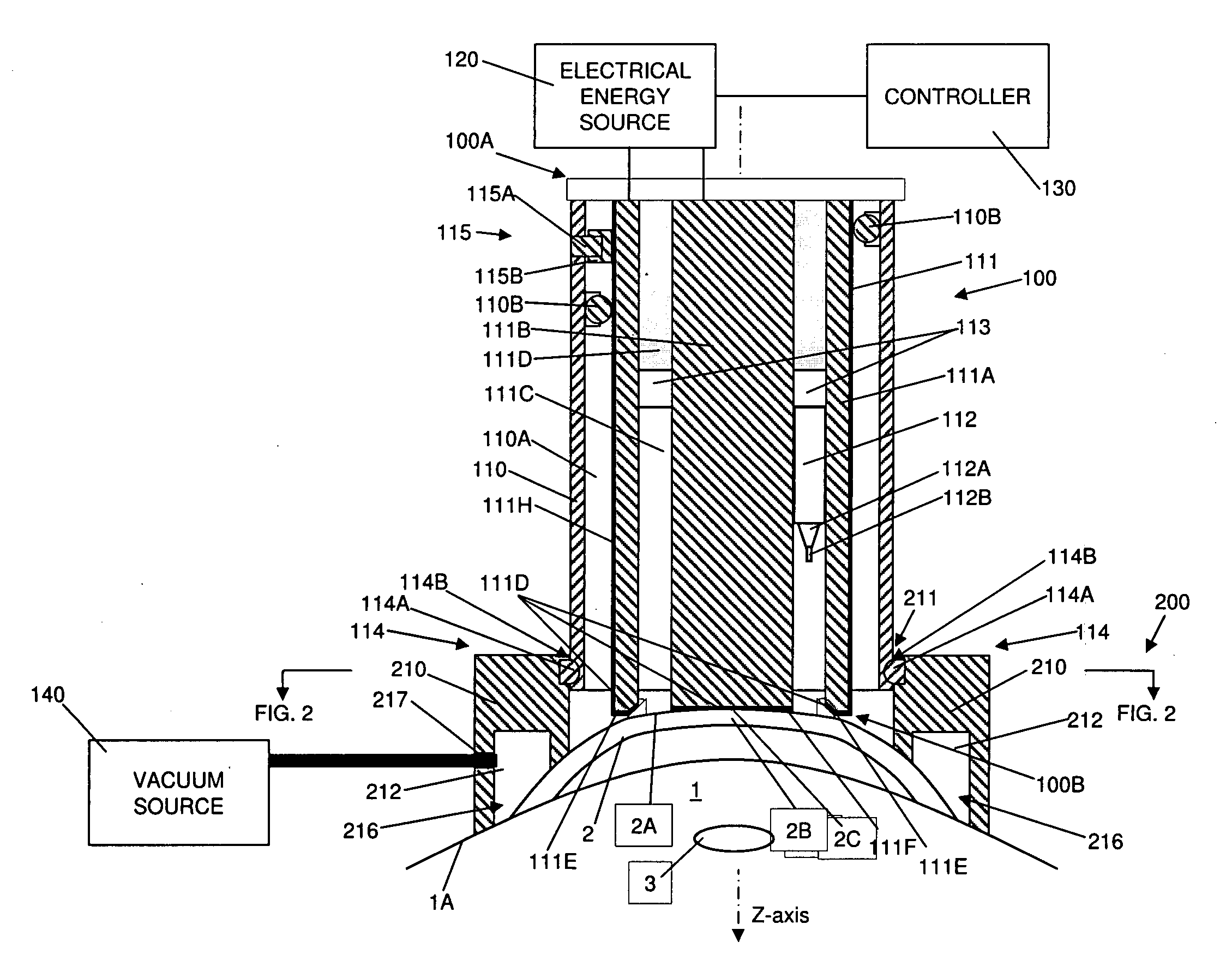
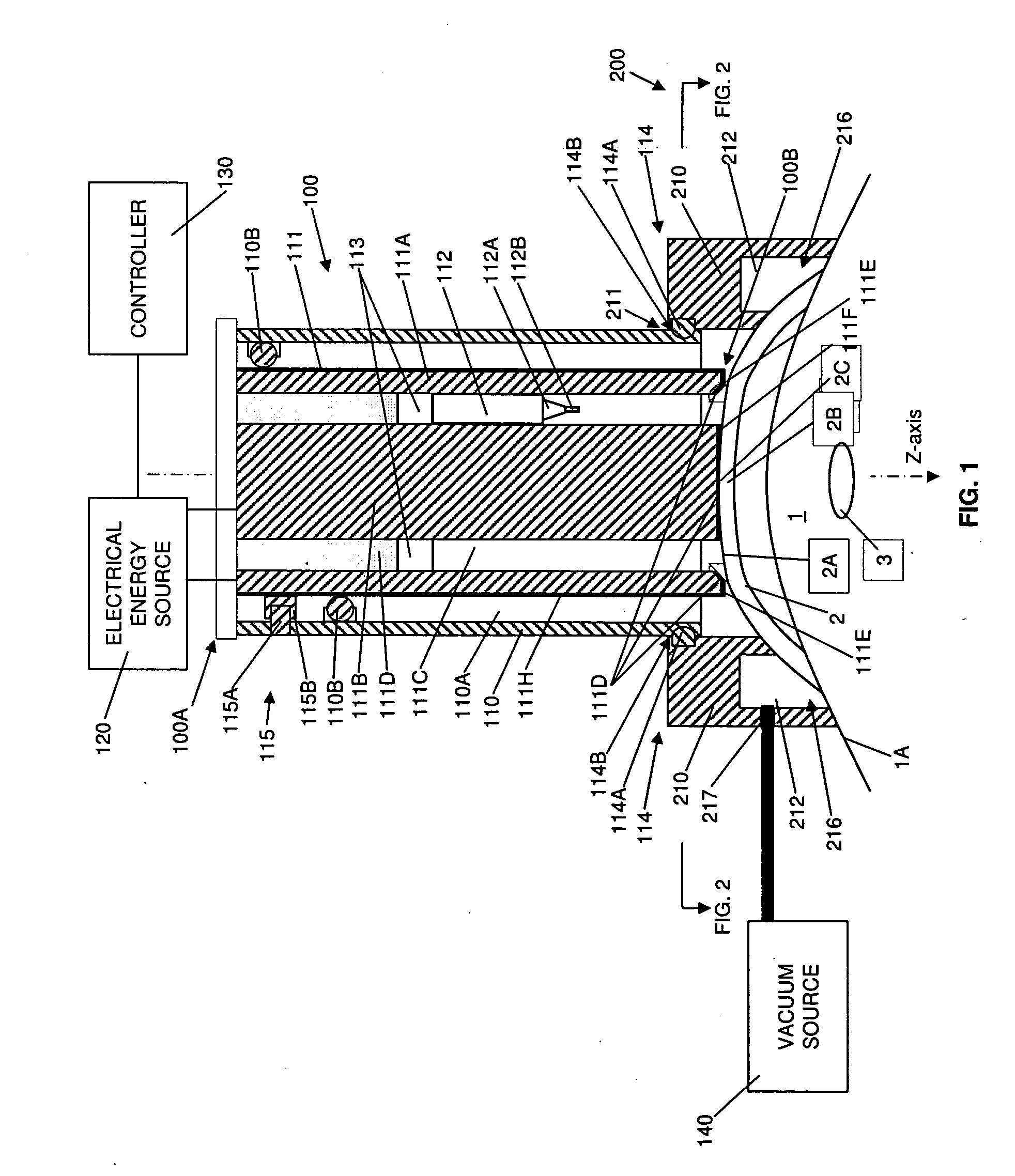
[0036]Referring to the cross-sectional view of FIG. 1, a system for applying energy to a cornea 2 of an eye 1 to achieve corrective reshaping of the cornea is illustrated. In particular, FIG. 1 shows an applicator 100 that includes a housing 110 and an energy conducting element 111, which extend from a proximal end 100A to a distal end 100B. The energy conducting element 111 is positioned within a passageway 110A which extends longitudinally through the housing 110. Any number of bearings 110B, or similar guiding structures, may be employed to keep the energy conducting element 111 substantially centered within the passageway 110A. An electrical energy source 120 is operably connected to the energy conducting element 111 at the distal end 100B, for example, via conventional conducting cables. The electrical energy source 120 may include a microwave oscillator for generating microwave energy. For example, the oscillator may operate at a microwave frequency range of 400 MHz to 3000 MH...


PUM


Abstract

A system for applying therapy to an eye includes an applicator having a conducting element configured to direct energy from an energy source to an application end of the conducting element, where the application end has at least one eye contact portion. A positioning system positions the at least one eye contact portion in stable engagement with the eye surface. The conducting element is disposed within a housing for the applicator and at least one adjustment system is employed to move the conducting element relative to the housing. The at least one adjustment system enables controlled movement of the conducting element and the at least one eye contact portion against the corneal surface. In particular embodiments, sufficient contact between the applicator and the cornea is determined by causing applanation of the cornea. In other embodiments, at least one measurement device is employed to determine when sufficient contact has been established.

Description

CROSS REFERENCE TO RELATED APPLICATIONS[0001]This application is a Continuation-In-Part (CIP) Application of U.S. application Ser. No. 12 / 018,457, filed Jan. 23, 2008, the contents of which are incorporated herein by reference.BACKGROUND OF THE INVENTION[0002]1. Field of the Invention[0003]The invention pertains generally to the field of keratoplasty and, more particularly, to a system and method for accurately and consistently applying a thermokeratoplasty applicator to the cornea.[0004]2. Description of Related Art[0005]A variety of eye disorders, such as myopia, keratoconus, and hyperopia, involve abnormal shaping of the cornea. Keratoplasty reshapes the cornea to correct such disorders. For example, with myopia, the shape of the cornea causes the refractive power of an eye to be too great and images to be focused in front of the retina. Flattening aspects of the cornea's shape through keratoplasty decreases the refractive power of an eye with myopia and causes the image to be pr...

Claims


Application Information

Patent Timeline
IPC IPC(8): A61B18/18A61B18/14
CPCA61B18/14A61B18/18A61B18/22A61B2018/00029A61B2018/00083A61B2018/1405A61F2009/00872A61B2019/2292A61B2019/465A61F9/0079A61F9/009A61F2009/00853A61B2018/1807A61B34/76A61B2090/065
Inventor MULLER, DAVIDSCHARF, RONALDRYAN, THOMASMARSHALL, NEALWU, ARTIE
Owner AVEDRO
Why Eureka
Try Eureka