
Ferroelectric ceramic material with a low sintering temperature

a technology of ferroelectric ceramics and low sintering temperature, which is applied in the field of ferroelectric materials, can solve the problems of high manufacturing cost, high cost of electrode layers made of these precious materials, and device failure, and achieve the effects of suppressing the formation of pyrochlore phase, low cost, and promoting the formation of perovskite phas

Active Publication Date: 2007-10-18
AGENCY FOR SCI TECH & RES
View PDF4 Cites 17 Cited by
  • Summary
  • Abstract
  • Description
  • Claims
  • Application Information

AI Technical Summary

Benefits of technology

[0012] In accordance with a second aspect of the present invention, there is provided a method for preparing a ferroelectric ceramic material, which may be used for fabricating electronic components or devices with a sintering temperature lower than that of the conventional ferroelectric ceramic material. Upon sintering, devices formed of the ferroelectric ceramic materials prepared according to embodiment of the present invention possess excellent piezoelectric properties. Devices fabricated thereof are suitable for many industrial applications including, for examples, bulk ferroelectric ceramics, ferroelectric ceramic thick films and ferroelectric multilayer ceramic devices.
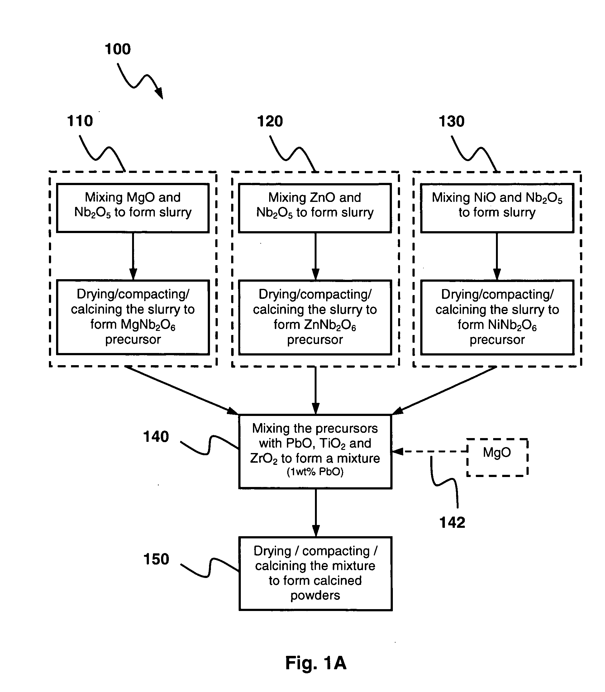
[0014] According to one embodiment, during mixing of the MgNb2O6, ZnNb2O6 and NiNb2O6 powder precursors with the PbO, TiO2 and ZrO2, an excess amount of oxides of valence 2 metal elements, for example MgO of 1% in mole, may be added. Addition of the excess amount of oxides of valence 2 metal elements helps promote the formation of perovskite phase and suppress the formation of pyrochlore phase in the ferroelectric ceramic material.
[0015] Ferroelectric ceramic materials according to embodiments of the present invention may be used to fabricate electronic devices in many industry applications. The sintering temperature is successfully reduced to a level suitable for the low cost Ag-based electrodes. In the meantime, electronic devices fabricated from the ferroelectric ceramic materials according to embodiments of the present invention possess advantageous physical, electrical and chemical properties.

Problems solved by technology

However, sintering at a high temperature significantly limits the application of ferroelectric ceramic material and leads to high manufacturing costs, and even cause device failures.
The cost of the electrode layers made of these precious materials is high, which can amounts to up to 80% of the total material costs of the multilayer devices.
However, this approach is difficult to implement because the high silver-content alloy and base metal cannot sustain the sintering temperature required for the conventional ferroelectric ceramic materials, when the sintering process is carried out in oxygen ambient.
However, this sintering temperature will cause serious inter-diffusion and oxidation of the metal electrode layer and substrate, which may result in failure in the integration of a ferroelectric ceramic thick film on a metallized substrate.
While these approaches may reduce the sintering temperature, the properties of the ferroelectric ceramic devices, in particular the piezoelectric properties of the sintered material are seriously compromised.
As such, ferroelectric ceramic materials prepared by these approaches may not satisfy the requirements for fabricating the electronic or electromechanical devices.
However, an ideal this type of ferroelectric ceramic material is currently unavailable.

Method used


Image

  • Ferroelectric ceramic material with a low sintering temperature
  • Ferroelectric ceramic material with a low sintering temperature
  • Ferroelectric ceramic material with a low sintering temperature

Examples


example 1

[0032] As illustrated in FIG. 1A, a preparation method 100 of the ferroelectric ceramic material of composition C5 with the composition as specified in Table 1 (0.10PNN-0.35PZN-0.15PMN-0.10PZ-0.30PT) starts from the synthesis of MgNb2O6 (MNO), ZnNb2O6 (ZNO) and NiNb2O6 (NNO) powder precursors.

[0033] To prepare MNO powder precursors, as shown in block 110, stoichiometric amount of high purity starting oxides, MgO (Kanto Chemical, 99.99%) and Nb2O5 (Kanto Chemical, 99.95%) are mixed in ethanol using a planetary ball mill for 24 hours, in an agate container with agate balls as the grinding media. The milled powders are then dried at 70° C. and collected through a 45 μm sieve. These powders are compacted and calcined at a temperature of 950° C. to 1050° C., for example about 1000° C., for 2 hours to form single columbite phase according to the X-Ray Diffraction (XRD) result (not shown). The calcined powders are then crushed and milled in ethanol for 8 hours using the same agate contain...

example 2

[0041] Another composition C4 as specified in Table 1 (0.20PNN-0.20PZN-0.10PMN-0.15PZ-0.35PT), may be produced through the same processing route as described in Example 1.

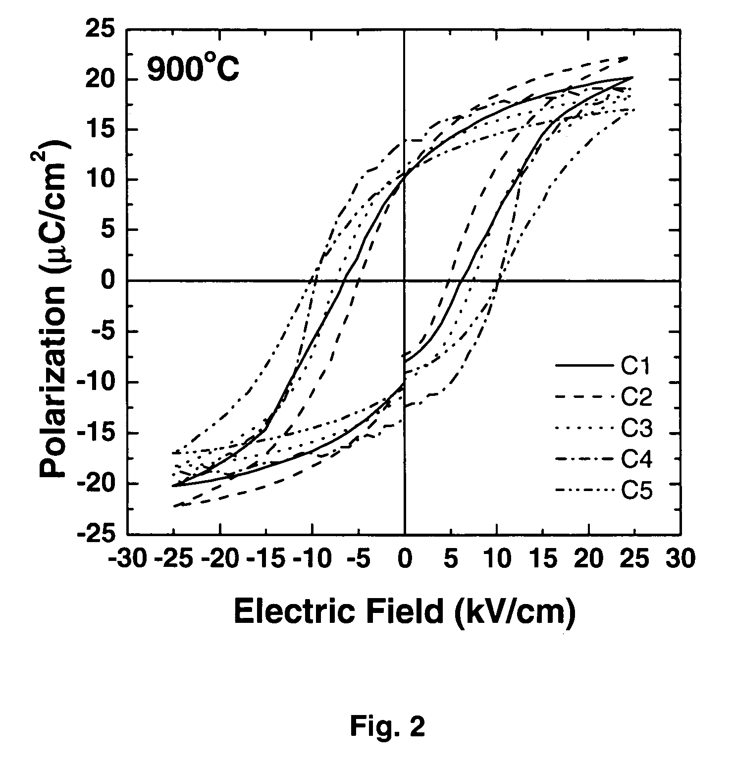
[0042] As shown in Table 2, the density of C4 test sample increases from 6.87 to 7.59 g / cm3, when the sintering temperature increases from 800 to 850° C. Upon sintering at a higher temperature above 850° C., the density does not increase but slightly declines. However, the maximum dielectric constant and piezoelectric coefficient for C4 are obtained after sintering at 900° C., which are 1900 (1 kHz) and 357 pC / N (FIG. 3), respectively. The remnant polarization increases with sintering temperature until 950° C., and is 13.9 μC / cm2 after sintering at 900° C. (Table 2 and FIG. 2). Temperature dependence of the dielectric constant indicates that this composition has a Curie temperature of 219° C., as shown in FIG. 4.

example 3

[0043] Another ceramic composition C3 as specified in Table 1 (0.30PNN-0.10PZN-0.10PMN-0.15PZ-0.35PT), may be produced through the same processing route as described in Example 1.

[0044] As shown in Table 2, the density of C3 test sample increases from 6.46 to 7.63 g / cm3 when sintering temperature increases from 800 to 850° C. Upon sintering at a higher temperature of above 850° C., the density does not increase but slightly declines. However, the maximum dielectric constant for C3 is obtained after sintering at 900° C., which is 2233 at 1 kHz. The remnant polarization and piezoelectric coefficient increase with sintering temperature until 950° C., and they are 13.6 μC / cm2 and 376 pC / N, respectively, as listed in Table 2. Temperature dependence of the dielectric constant indicates that this composition has a Curie temperature of 183° C., as shown in FIG. 4.


PUM

PropertyMeasurementUnit
temperatureaaaaaaaaaa

Abstract

The present invention provides new ferroelectric ceramic materials which can be sintered at a temperature lower than that of the conventional ferroelectric ceramic materials and upon sintering, devices formed of the new ferroelectric ceramic materials possesses excellent piezoelectric properties which are suitable for many industrial applications. The ferroelectric ceramic material includes a composition with a general formula of wPb(Ni1 / 3Nb2 / 3)O3−xPb(Zn1 / 3Nb2 / 3)O3−yPb(Mg1 / 3Nb2 / 3)O3−zPbZrO3−(1−w−x−y−z)PbTiO3, in which 0<w<1, 0<x<1, 0≦y<1, 0<z<1, w+x+y+z<1, and 0.5≦w+x+y. A method of preparing a ferroelectric ceramic material includes preparing MgNb2O6, ZnNb2O6 and NiNb2O6 powder precursors, mixing the precursors with PbO, TiO2 and ZrO2 to form a mixture and calcining the mixture.

Description

FIELD OF THE INVENTION [0001] The present invention relates to ferroelectric materials. In particular, it relates to ferroelectric ceramic materials with a low sintering temperature. BACKGROUND OF THE INVENTION [0002] Ferroelectric ceramic materials are used in various industrial applications as dielectric media to produce electronic components or devices such as piezoelectric sensors, actuators, transducers, capacitors and pyroelectric sensors. [0003] During the manufacturing process of these devices, ferroelectric ceramic materials is are to undergo a sintering process at a high temperature. For example, at a temperature of about 1000° C. or higher. However, sintering at a high temperature significantly limits the application of ferroelectric ceramic material and leads to high manufacturing costs, and even cause device failures. [0004] For example, in the manufacturing process of multilayer capacitors and actuators, dielectric layers made of ferroelectric ceramic materials are co-...

Claims


Application Information

Patent Timeline
Patent Type & Authority Applications(United States)
IPC IPC(8): C04B35/00H01L41/273H01L41/39
CPCC04B35/493C04B2235/81C04B35/6262C04B35/62675C04B2235/3206C04B2235/3244C04B2235/3248C04B2235/3251C04B2235/3255C04B2235/3279C04B2235/3284C04B2235/656C04B2235/768C04B2235/77C04B35/499
Inventor YAO, KUIGAN, BEE KEEN
Owner AGENCY FOR SCI TECH & RES
Learn More