Dry sump oil tank assembly for a vehicle

a technology for sump tanks and vehicles, which is applied in the direction of mechanical equipment, machines/engines, lubrication of auxiliaries, etc., can solve the problems of lowering the lubricating efficiency of oil, entrapped air, etc., and achieves the effect of increasing the overall volume of the internal cavity, increasing the height of the housing, and adding lateral volume to the internal cavity

Active Publication Date: 2009-08-27
GM GLOBAL TECH OPERATIONS LLC
View PDF6 Cites 23 Cited by
  • Summary
  • Abstract
  • Description
  • Claims
  • Application Information

AI Technical Summary

Benefits of technology

[0005]A dry sump oil tank assembly is provided for lubricating an engine, and is suitable for a high performance vehicle, such as a racing vehicle or for a standard passenger vehicle that may occasionally be subjected to high-performance conditions. The dry sump oil tank assembly includes a housing that defines an internal cavity. The housing is configured with a laterally-extending portion in order to add lateral volume to the internal cavity. Thus, the overall volume of t

Problems solved by technology

Entrained air lowers the lubr

Method used


Image

  • Dry sump oil tank assembly for a vehicle
  • Dry sump oil tank assembly for a vehicle
  • Dry sump oil tank assembly for a vehicle

Examples


Embodiment Construction

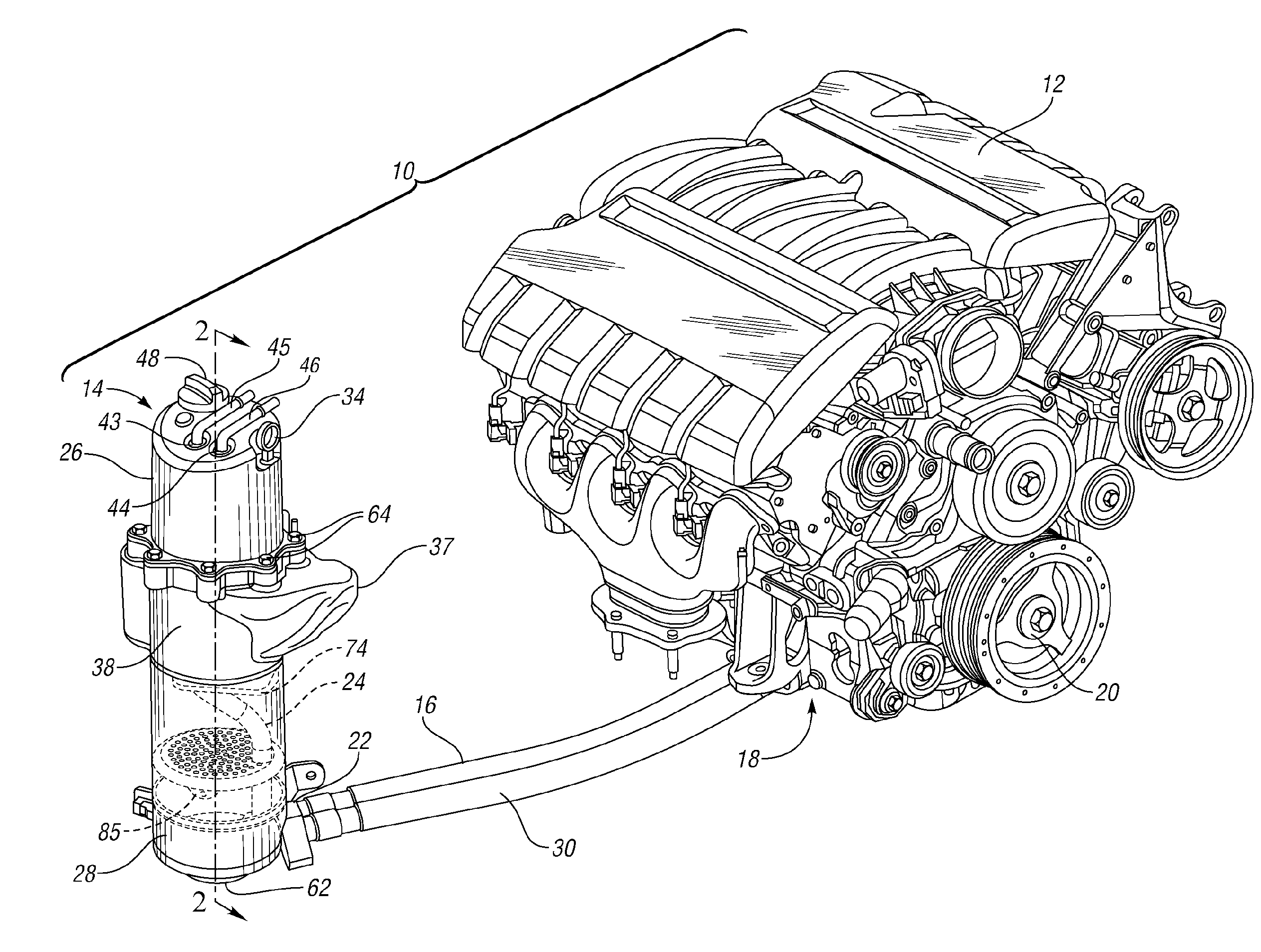
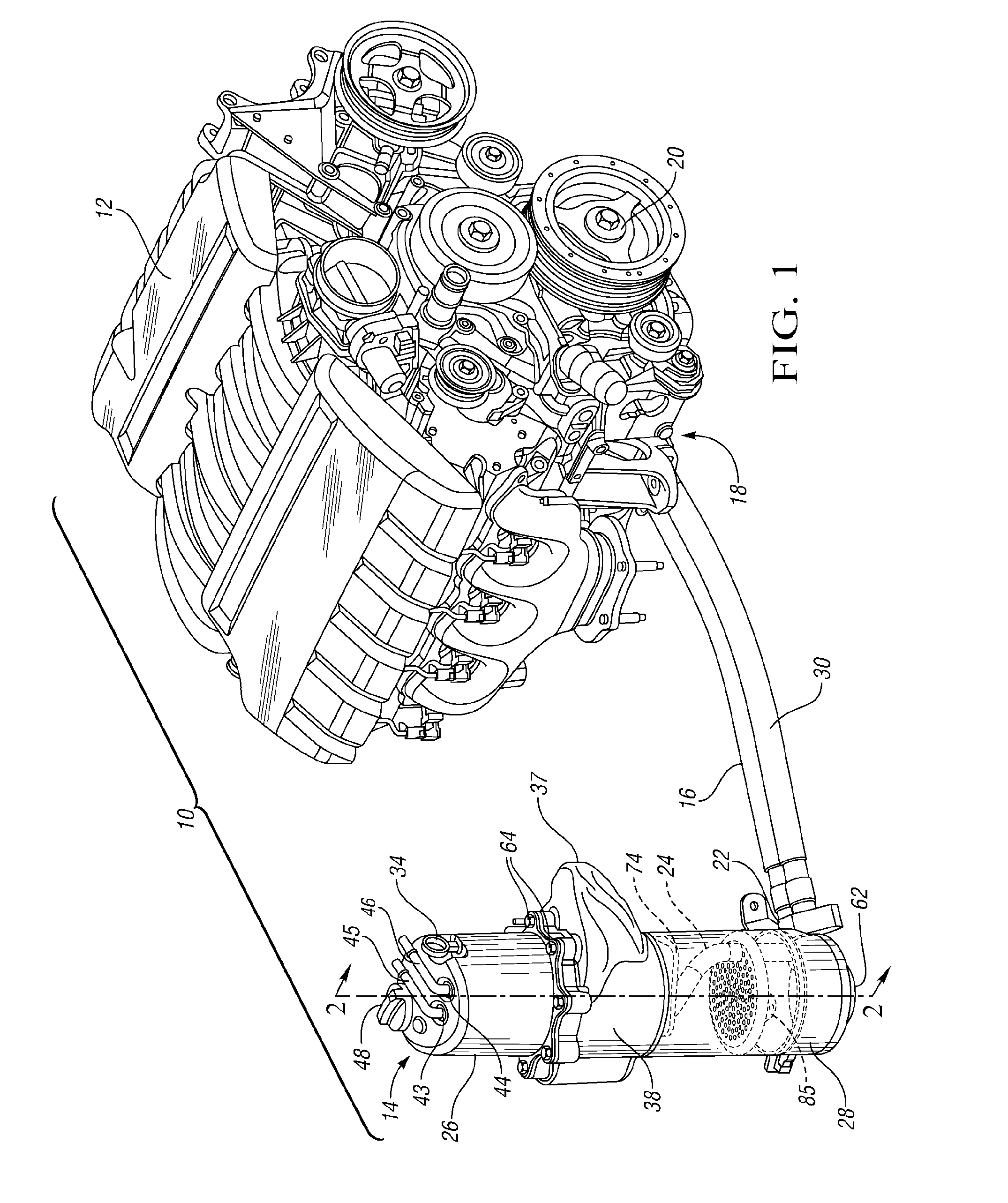
[0012]Referring to the drawings wherein like reference numbers refer to like components, FIG. 1 shows a portion of a vehicle 10 including an engine 12 connected with a dry sump oil tank assembly 14. An oil supply hose 16 feeds oil collected in a sump 18 at the bottom of the engine 12 to the dry sump oil tank assembly 14. A pump assembly, not visible in FIG. 1, driven by the engine crankshaft 20 forces the oil through the oil supply hose 16 to an oil inlet 22 of the dry sump oil tank assembly 14. A connecting hose 24 directs oil from the oil inlet 22 to a separator 26, where the oil is deaerated and air for a positive crankcase ventilation (PCV) system is separated from any entrained oil, as discussed further with respect to FIG. 2. The deaerated oil drains to a lower housing portion 28, where it is returned via an oil return hose 30 to the oil pump assembly for reuse in lubricating the engine 12. The pump assembly includes a pressure section that draws the deaerated fluid from the d...


PUM


Abstract

A dry sump oil tank assembly for a vehicle is provided with a housing defining an internal cavity. The housing is configured with a laterally-extending portion to add lateral volume to the internal cavity and has at least one internal baffle attached to the housing within the internal cavity below the laterally-extending portion and configured to reduce sloshing of oil within the cavity. The dry sump oil tank assembly is particularly useful for high performance applications, such as racing vehicles, and may utilize components from standard vehicle applications, thus maximizing the economies of scale of producing such components and being suited for a vehicle that may be typically used in standard driving conditions, but occasionally subjected to high performance use.

Description

TECHNICAL FIELD[0001]The invention relates to a dry sump tank assembly that has at least one internal baffle configured to reduce oil slosh and extended lateral volume to allow a higher level of oil during operation.BACKGROUND OF THE INVENTION[0002]Lubrication systems for internal combustion engines on passenger vehicles may be wet or dry sump lubrication systems. A wet sump lubrication system is typically used on production vehicles. Lubricant is stored beneath the crankshaft and oil pan. The oil pan needs to be large and deep in order to hold sufficient amounts of lubricant, such as oil, to lubricate the engine.[0003]Dry sump lubrication systems utilize an external tank to store some of the oil outside of the engine. Accordingly, a large and deep oil pan under the engine is not required. Therefore, the main mass of the engine may be placed lower in the vehicle. Dry sump lubrication systems are commonly used with high-performance engines, such as racing vehicles.[0004]In vehicles w...

Claims


Application Information

Patent Timeline
IPC IPC(8): F01M1/12F01M13/04F01M1/02
CPCF01M1/12F01M2011/0083F01M2001/126
Inventor PRIOR, GREGORY P.ZAHDEH, AKRAM R.MCALPINE, ROBERT S.MAZZOLA, BRYCE E.
Owner GM GLOBAL TECH OPERATIONS LLC
Why Eureka
Try Eureka