Binary Signal Detection

a signal detection and signal technology, applied in plasma welding apparatus, welding coupling means, manufacturing tools, etc., can solve the problems of easy repair of damaged torch, unintuitive manual adjustment, and trade-offs in machine performan

Inactive Publication Date: 2009-08-27
HYPERTHERM INC
View PDF27 Cites 27 Cited by
  • Summary
  • Abstract
  • Description
  • Claims
  • Application Information

AI Technical Summary

Benefits of technology

[0007]The invention, in one aspect, includes a system for identifying a torch assembly associated with a thermal processing system. The system can include a detector that detects a multi-bit binary signal based on a plurality of open circuits or closed circuits with the thermal processing system. The system can also include a control mechanism in communication with the detector, the control mechanism identifying at least one characteristic of the torch assembly based upon the multi-bit binary signal. The system can include one ore more single, binary physical components (e.g., a pin, a jumper between two pins, etc.) that can form the basis for the multi-bit binary signal based on a plurality of open circuits or closed circuits.

Problems solved by technology

Second, it is easy to repair a damaged torch.
Some of the disadvantages of a removable torch are that different lead lengths need different regulator pressure, different lead lengths need different start timing, machine torches and hand torches need to be distinguished for safety reasons, machine torch configurations need to activate remote pendant control, and different torches with the same connector can have different amperage levels.
To accommodate different lead lengths, tradeoffs can be made in machine performance, or unintuitive manual adjustments have to be made.
Additionally, long lead lengths may not be offered because of starting limitations.
However, pin rearrangement to mechanically inhibit interchangeability can be limited in the number of combinations.
Measuring a resistance or impedance can be undesirable, as the electrical components can be vulnerable to corrosion, affecting the ability to measure resistance or impedance, which affects accuracy.
Utilizing a microchip or a circuit can be costly, require several parts to manufacture, and may not be sufficiently robust for an industrial environment.

Method used


Image

  • Binary Signal Detection
  • Binary Signal Detection
  • Binary Signal Detection

Examples


Embodiment Construction

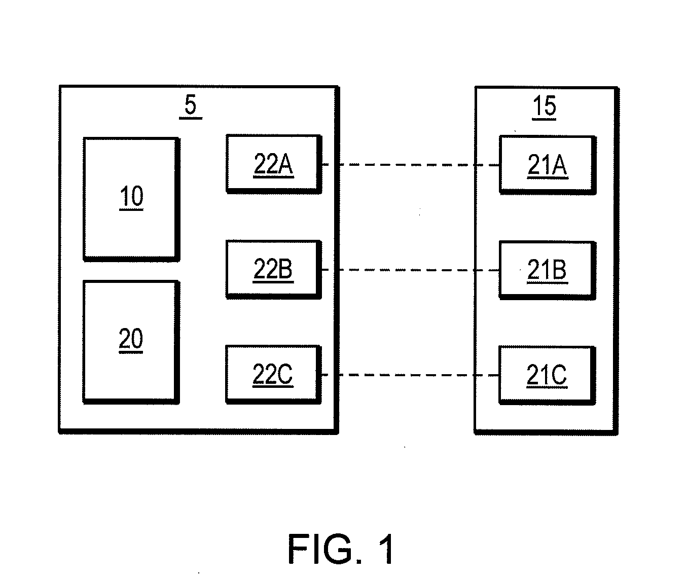
[0031]FIG. 1 is a schematic drawing of an identification module 5 according to an illustrative embodiment. An identification module 5 includes a detector 10 that detects a multi-bit binary signal based on at least one of an open circuit or closed circuit signal when the identification module 5 is connected to a device 15 associated with a thermal processing system. The identification module 5 also includes a control mechanism 20 in communication with the detector 10. The control mechanism 20 can receive a multi-bit binary signal based on a detected open circuit, detected closed circuit signal or any combination thereof, a bit pattern of the multi-bit binary signal identifying at least one characteristic of the device 15 associated with the thermal processing system. The binary signal can be processed to produce a bit pattern or a binary code. The control mechanism 20 can process a multi-bit binary-signal based at least one of the open or closed circuits, wherein a bit pattern of the...


PUM

PropertyMeasurementUnit
pressureaaaaaaaaaa
currentaaaaaaaaaa
poweraaaaaaaaaa

Abstract

A system and method for identifying a torch assembly associated with a thermal processing system can include a detector that detects a multi-bit binary signal based on a plurality of open circuits or closed circuits with the thermal processing system. Each representative binary signal can comprise an individual physical component. The system can also include a control mechanism in communication with the detector, the control mechanism identifying at least one characteristic of the torch assembly based upon the multi-bit binary signal.

Description

FIELD OF THE INVENTION[0001]The invention relates to identifying characteristics of a thermal processing system. Specifically, the invention relates to binary signal detection of device associated with a thermal processing system.BACKGROUND OF THE INVENTION[0002]The two main components of a plasma arc torch systems and welding equipment are a torch assembly and a power supply assembly. The torch can be affixed to a power supply using one of two methods. In the first method, the torch can be plumbed inside the unit and can only be changed by using a tool to enter the power supply. In the second method, the torch can be attached to a power supply using a detachable connector assembly.[0003]A detachable connector assembly can provide some advantages. First, it is simple to exchange hand and machine style torches or different length torches. Second, it is easy to repair a damaged torch. Third, it may be more convenient to store a detached torch separate from the power supply.[0004]Some ...

Claims


Application Information

Patent Timeline
Patent Type & Authority Applications(United States)
IPC IPC(8): B23K9/32B23K10/00
CPCB23K9/0953B23K9/323H05H2001/3473B23K15/02H05H1/36B23K15/0026H05H1/3473
Inventor BOROWY, DENNIS M.ROBERTS, JESSE A.
Owner HYPERTHERM INC
Why Eureka
Try Eureka