Light beam scanning device

a scanning device and beam technology, applied in optics, instruments, electrical equipment, etc., can solve the problems of low polygon mirror productivity, easy shrinkage, and inability to miniaturize the scanning devi

Inactive Publication Date: 2009-08-27
SANKYO SEIKI MFG CO LTD
View PDF1 Cites 11 Cited by
  • Summary
  • Abstract
  • Description
  • Claims
  • Application Information

AI Technical Summary

Problems solved by technology

However, in the conventional light beam scanning device, a diameter of a light beam which is incident on a polygon mirror is large, the polygon mirror is required to have a further larger size.
Therefore, in the conventional light beam scanning device, since a size of the polygon mirror cannot be reduced, there are problems that a light beam scanning device cannot be miniaturized and productivity of the polygon mirror is low.
Further, when a polygon mirror will be manufactured by utilizing resin molding, shrinkage easily occurs and it is difficult to improve productivity and yield.
Moreover, when the polygon mirror is driven by a motor, it is difficult to be balanced to cause a jitter characteristic to deteriorate.
However, like a conventional case, when a light beam having a large diameter is used, cost is extremely increased and the merits of a microminiaturized reflector plate cannot be utilized.

Method used


Image

  • Light beam scanning device
  • Light beam scanning device
  • Light beam scanning device

Examples


first embodiment

(Entire Structure)

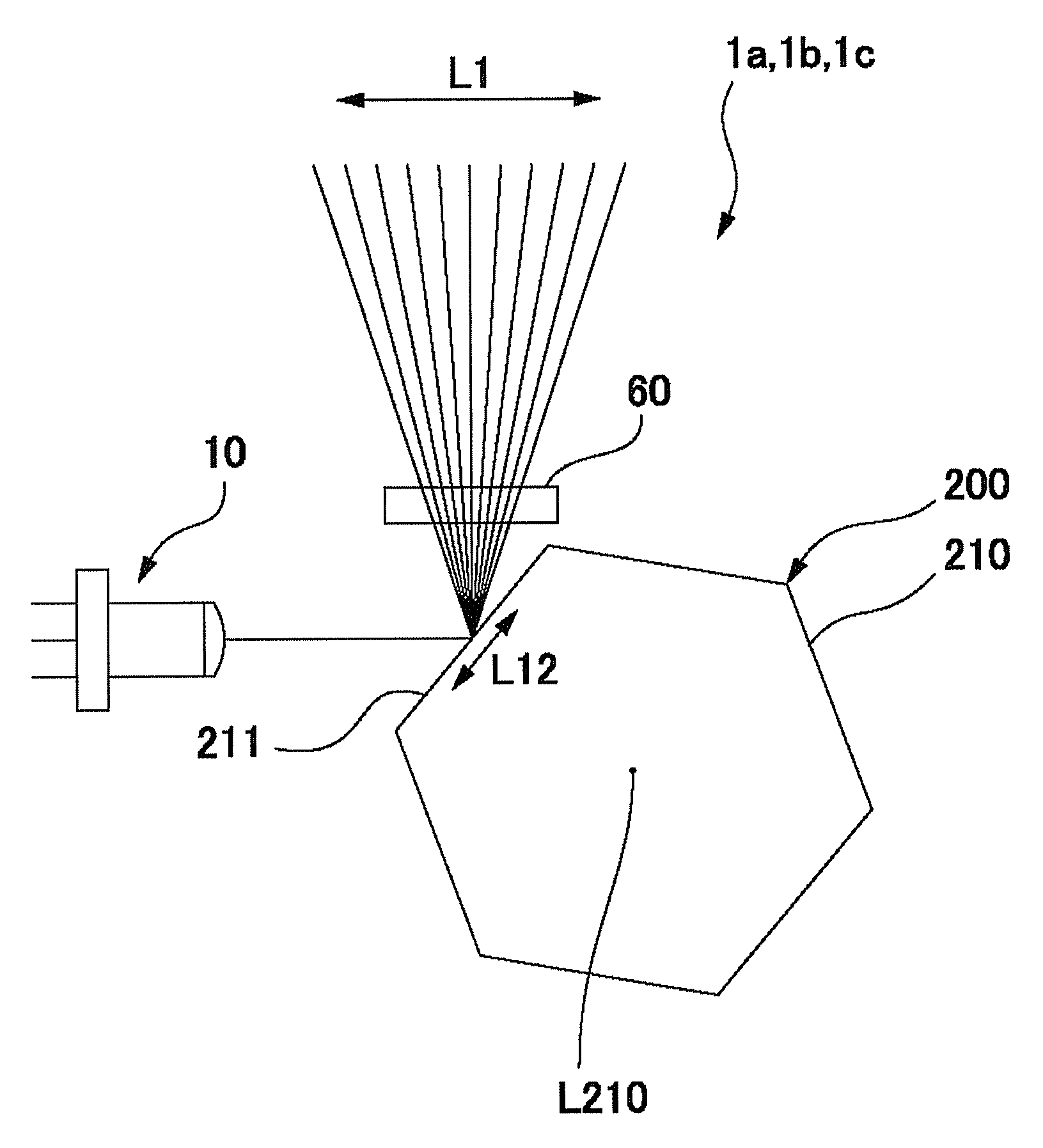
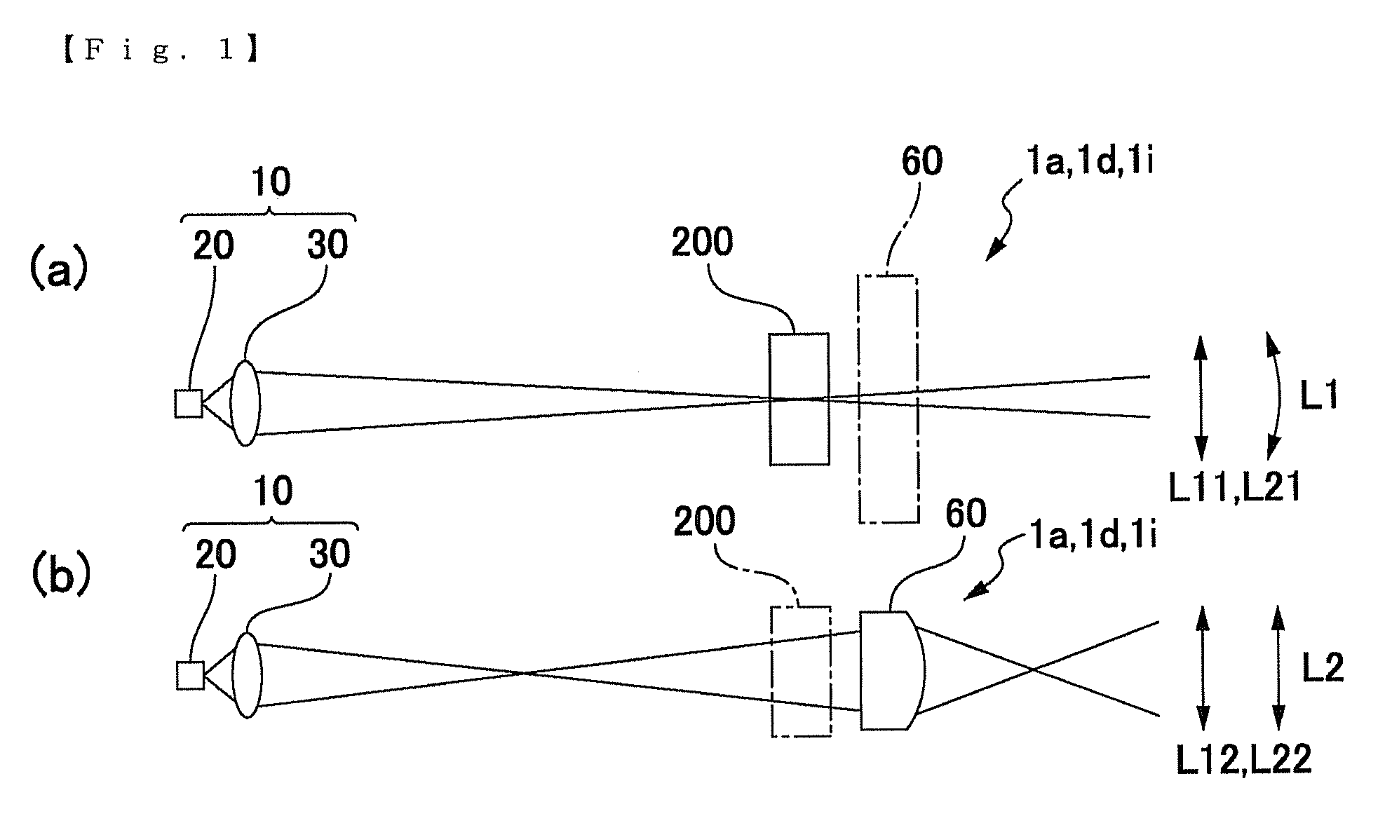
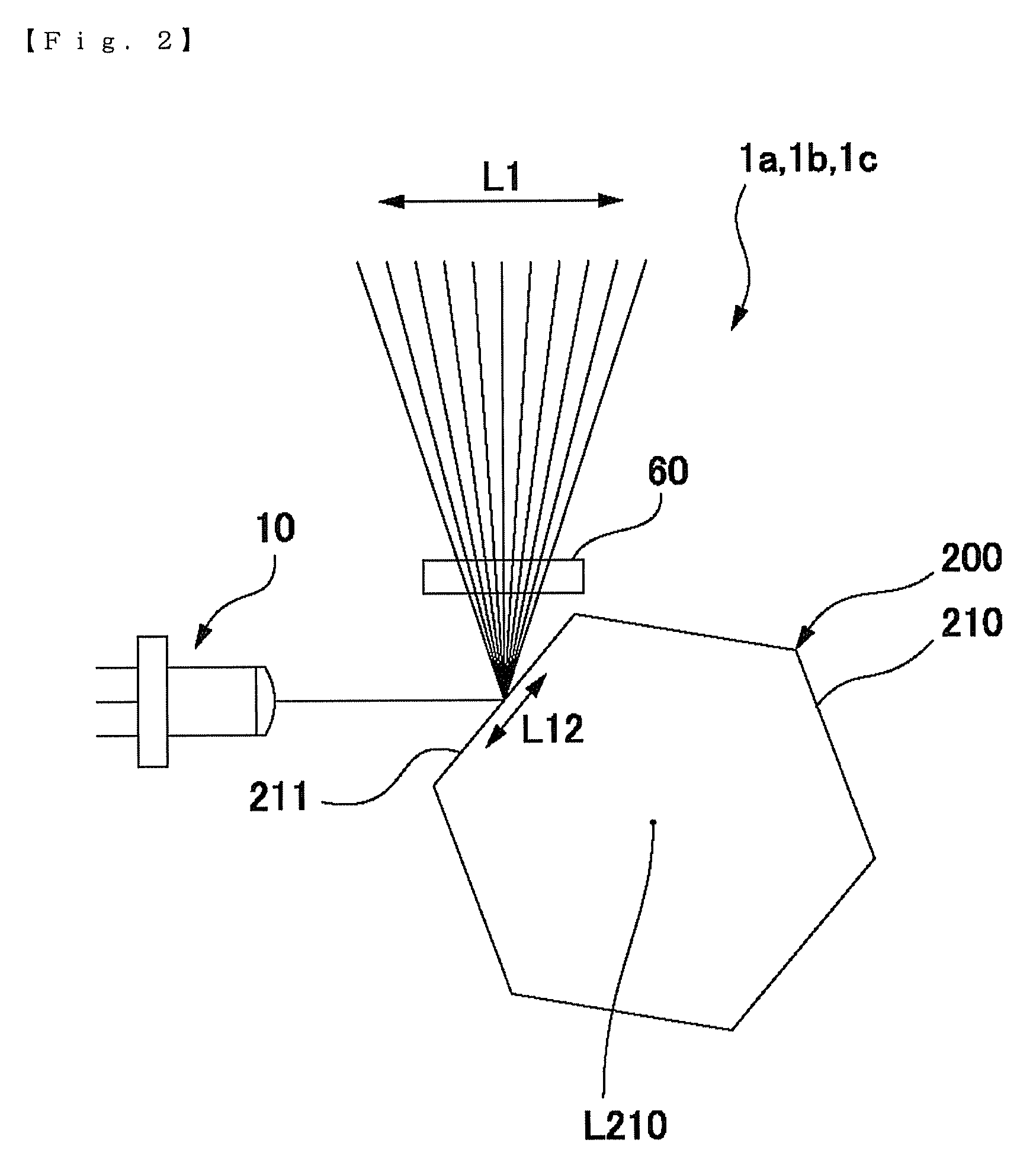
[0071]FIG. 1 is an explanatory view showing an optical structure of a light beam scanning device in accordance with a first embodiment of the present invention. FIG. 1(a) is an explanatory view in a scanning direction of a light beam and FIG. 1(b) is an explanatory view in a direction perpendicular to the scanning direction. FIG. 2 is an explanatory view showing a state where a light beam emitted from a light source device is irradiated to a polygon mirror in the light beam scanning device in accordance with the first embodiment of the present invention. FIG. 3 is an explanatory view showing a directional relationship between a convergent direction of the light beam and the polygon mirror in the light beam scanning device in accordance with the first embodiment of the present invention. In FIGS. 1(a) and 1(b), a solid line is illustrated in a direction where an optical deflection element exerts a deflection operation and an alternate long and short dash line is ill...

second embodiment

[0082]FIG. 4 is an explanatory view showing an optical structure of a light beam scanning device in accordance with a second embodiment of the present invention. FIG. 4(a) is an explanatory view in a scanning direction of a light beam and FIG. 4(b) is an explanatory view in a direction perpendicular to the scanning direction. FIG. 5 is an explanatory view showing a directional relationship between a convergent direction of the light beam and a polygon mirror in the light beam scanning device in accordance with the second embodiment of the present invention. A basic structure of the light beam scanning device in this embodiment is similar to that in the first embodiment and thus the same notational symbols are used for common portions and their detailed descriptions are omitted. Further, in FIGS. 4(a) and (b), similarly to FIGS. 1(a) and 1(b), a solid line is illustrated in a direction where an optical deflection element exerts a deflection operation and an alternate long and short d...

third embodiment

[0090]FIG. 6 is an explanatory view showing an optical structure of a light beam scanning device in accordance with a third embodiment of the present invention. FIG. 6(a) is an explanatory view in a scanning direction of a light beam and FIG. 6(b) is an explanatory view in a direction perpendicular to the scanning direction. FIG. 7 is an explanatory view showing a directional relationship between a convergent direction of the light beam and a polygon mirror in the light beam scanning device in accordance with the third embodiment of the present invention. A basic structure of the light beam scanning device in this embodiment is similar to that in the first embodiment and thus the same notational symbols are used for common portions and their detailed descriptions are omitted. Further, in FIGS. 6(a) and 6(b), similarly to FIGS. 1(a) and 1(b), a solid line is illustrated in a direction where an optical deflection element exerts a deflection operation and an alternate long and short da...


PUM


Abstract

A light beam scanning device may include a light source device, and an optical deflection mechanism for scanning a light beam which is emitted from the light source device over a prescribed angular range by an optical deflection element. The light source device may be provided with a light emitting source and a condenser lens for guiding the light beam emitted from the light emitting source as a converged light beam which is focused on the optical deflection element or its vicinity in at least one of a first direction and a second direction which are perpendicular to an optical axis direction. The light beam scanning device may further include a divergence angle modification lens for varying a divergence angle of an emitted light beam from the optical deflection element in at least a direction perpendicular to a scanning direction by the optical deflection element.

Description

TECHNICAL FIELD[0001]The present invention relates to a light beam scanning device for scanning a light beam emitted from a light source device in a prescribed direction.BACKGROUND ART[0002]Conventionally, light beam scanning devices have been widely used in an image forming device such as a laser printer, a digital copying machine and a facsimile, or a bar code reading device, an inter-vehicle distance measuring device and the like. In a light beam scanning device used in an image forming device, a light beam emitted from a laser beam emitting element such as a laser diode is periodically deflected by a polygon mirror to periodically scan on a surface to be scanned of a photosensitive body. On the other hand, in a measuring device, information is detected by receiving a reflected light beam with a photo-detector in which the reflected light beam is a scanning light beam emitted from a light beam scanning device and reflected by an object to be irradiated. In this case, the reflecte...

Claims


Application Information

Patent Timeline
Patent Type & Authority Applications(United States)
IPC IPC(8): G02B26/12
CPCG02B26/108H04N1/129H04N1/12G02B26/12
Inventor HAYASHI, KENICHI
Owner SANKYO SEIKI MFG CO LTD
Why Eureka
Try Eureka