Data Transmission Apparatus and Data Reception Apparatus

Inactive Publication Date: 2009-08-27
NAKAGAWA LAB INC
View PDF7 Cites 95 Cited by
  • Summary
  • Abstract
  • Description
  • Claims
  • Application Information

AI Technical Summary

Benefits of technology

[0014]According to the present invention, since transmission of data is possible without changing the pulse width of the PWM signal, average light power may be kept constant. Therefore, it is never seen as flickering to the human eye during data transmission, and quality data communication may be carried out even using conventional lighting control.
[0

Problems solved by technology

However, since the aforementioned lighting equipment, display device and the like need lighting control, the

Method used


Image

  • Data Transmission Apparatus and Data Reception Apparatus
  • Data Transmission Apparatus and Data Reception Apparatus
  • Data Transmission Apparatus and Data Reception Apparatus

Examples


first embodiment

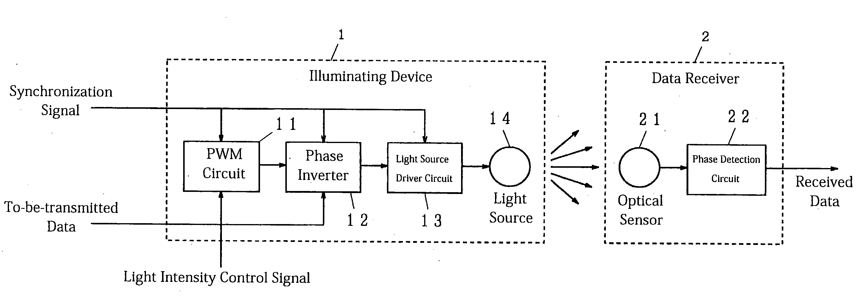
[0030]An example of an operation of the first embodiment according to the present invention is described forthwith. A light intensity control signal corresponding to a desired intensity of light is input to the PWM circuit 11. The PWM circuit 11 generates a PWM signal as shown in FIG. 11, for example.

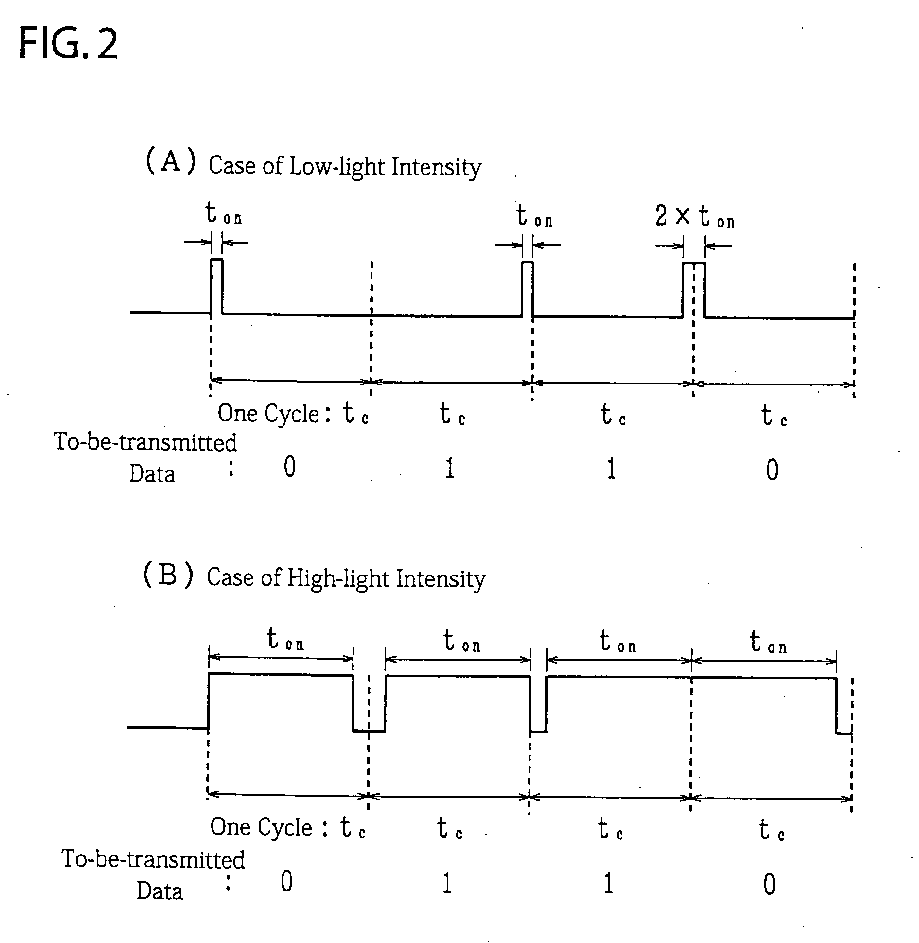
[0031]The generated PWM signal is transmitted to the phase inversion circuit 12, next. A to-be-transmitted data signal or a digital value made of Os and / or 1 s is input to the same phase inverter 12. The phase inverter 12 outputs the PWM signal directly when the to-be-transmitted data signal is 0, for example, whereas it outputs an inverted signal of the PWM signal when the to-be-transmitted data signal is 1. Needless to say that the phase may be inverted when the to-be-transmitted data signal is 0, whereas it may not be inverted and output when 1.

[0032]The light source driver circuit 13 generates a driving electric current in proportion to a signal from the phase inverter 12, which the...

second embodiment

[0054]Exemplified processing of the second embodiment according to the present invention is briefly described forthwith. The PWM circuit 11 generates a PWM signal based on a light intensity control signal corresponding to the observed light intensity. The generated PWM signal is then transmitted to the rising edge timing control circuit 15. The rising edge timing control circuit 15 controls the rising edge of the PWM signal in conformity with to-be-transmitted data; more specifically, it controls so that the rising edge falls in a time slot for the to-be-transmitted data as shown in FIG. 6, for example. The light source driver circuit 13 drives the light source 14 in conformity with this signal, and the light source 14 then emits a visible light modulated based on the to-be-transmitted data. In sync therewith, the synchronization signal light source 16 is driven according to a synchronization signal, emitting an synchronization infrared light signal.

[0055]In the data receiver 2, the...

third embodiment

[0063]Exemplified processing of the third embodiment according to the present invention is briefly described forthwith. The PWM circuit 11 generates a PWM signal based on a light intensity control signal corresponding to an observed light intensity. The generated PWM signal is transmitted to the phase inverter 12, which then inverts the phase thereof according to to-be-transmitted data appropriately. The phase-inverted PWM signal is transmitted to the oscillator 17, which then. generates a signal oscillating with a subcarrier frequency when the pulse signal is in an ON state. As a result, signals as shown in FIG. 8, for example, are generated. FIG. 8(A) shows the case of low-light intensity, while FIG. 8(B) shows the case of high-light intensity. In either case, a waveform with the subcarrier frequency is generated while the respective signals shown in FIG. 2 are in an ON state. In conformity with this signal, the light source driver circuit 13 drives the light source 14, which thus...


PUM


Abstract

A data communication system capable of controlling the brightness of light sensed by the human eye and quality communication using an illuminative light is provided. A PWM circuit 11 adjusts pulse width in conformity with a light intensity control signal corresponding to a desired light intensity, resulting in a PWM signal. The PWM signal is then transmitted to a phase inverter 12. The phase inverter 12 outputs the PWM signal as is when a data signal to be transmitted is 0, for example, while it inverts the phase of the PWM signal and then outputs the resulting inverted PWM signal when the data signal is 1. A light source driver circuit 13 drives, a light source 14 such as an LED, organic electroluminescence, or the like in conformity with the phase inverted signal to emit light. In a data reception unit 2, an optical sensor 21 converts light emitted from an illuminating device 1 to an electric signal. A phase detection circuit 22 detects the phase of the signal and then outputs a received data signal.

Description

TECHNICAL FIELD[0001]The present invention relates to a communication technique that uses light radiated from lighting equipment or a display device through the air for communication.BACKGROUND ART[0002]New devices such as light emitting diodes (LEDs) or organic electroluminescence used as a light source for lighting equipment or display devices have been developed. Lighting equipment utilizes visible light itself radiated from such devices as an illuminative light source. Regarding display devices, LED and organic electroluminescence are considered to be used as a light source for back lights of a liquid crystal display, and are already used in a few applications.[0003]Lighting equipment and display devices need lighting control. For example, in the case of lighting equipment, light sources thereof need lighting control so as to adjust brightness in the room. Meanwhile, the display devices need the following two types of controls. The first type is to adjust brightness of the displ...

Claims


Application Information

Patent Timeline
IPC IPC(8): H04B10/04H05B37/02H04B10/11H04B10/116H04B10/524H04B10/556
CPCH04B10/1149H04B10/116Y02B20/346H05B33/0869H05B33/0818H05B45/22F21Y2115/15F21Y2105/00Y02B20/30
Inventor NAKAGAWA, MASAOHARUYAMA, SHINICHIRO
Owner NAKAGAWA LAB INC
Why Eureka
Try Eureka