Reslution optical & ultrasound devices for imaging and treatment of body lumens

a technology of optical & ultrasound and body lumen, which is applied in the field of improvement of devices for intravascular ultrasound and optically guided catheter systems, can solve the problems of poor quality image, poor quality image, and difficulty in realizing a driving mechanism while keeping the catheter fully flexible and steerable, and achieves the effect of higher resolution

Inactive Publication Date: 2009-08-27
LENKER JAY A
View PDF48 Cites 124 Cited by
  • Summary
  • Abstract
  • Description
  • Claims
  • Application Information

AI Technical Summary

Benefits of technology

[0009]An embodiment of the invention comprises a catheter comprising an array of ultrasound transducers and actuators along with signal processing, display, and power subsystems. The actuators on the catheter cause the array to oscillate. This allows the array to produce more imaging points of the object to be viewed than a non-rotating or a stationary array. Additional computer processing of the ultrasound data produces an image with a higher resolution than images produced from data from a non-oscillating transducer array.

Problems solved by technology

When the data is processed, gaps of missing information occur, resulting in a poor quality image.
The stationary catheters are reliable and inexpensive but produce a poor quality image.
Realizing a driving mechanism while keeping the catheter fully flexible and steerable as well as miniature are challenging problems.
Distortion of the image due to an unequal rotation of the element or mirror at the catheter tip is a limitation of these systems.
The mechanically rotating devices produce an acceptable image but are unreliable and expensive.

Method used


Image

  • Reslution optical & ultrasound devices for imaging and treatment of body lumens
  • Reslution optical & ultrasound devices for imaging and treatment of body lumens
  • Reslution optical & ultrasound devices for imaging and treatment of body lumens

Examples


Embodiment Construction

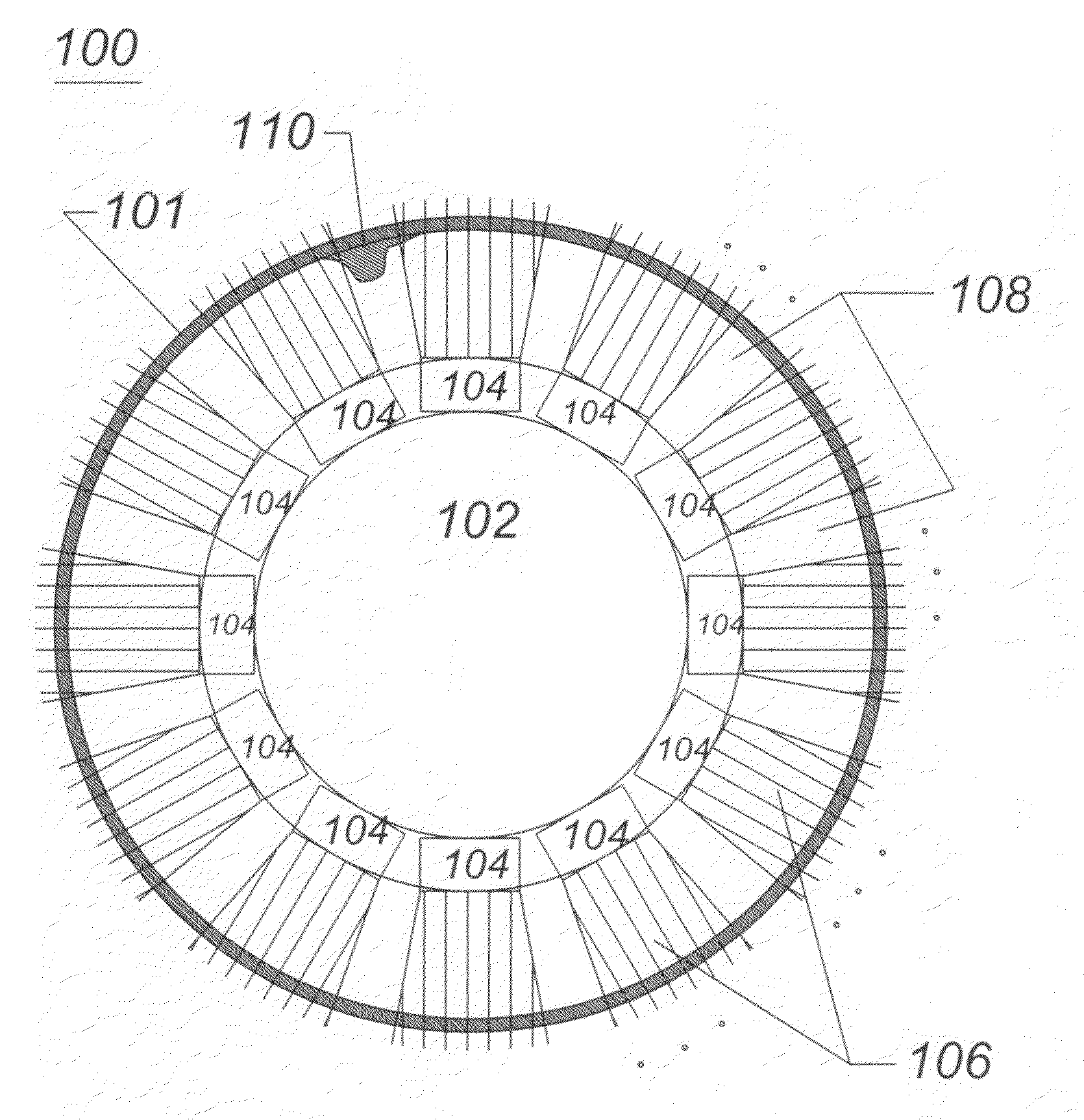
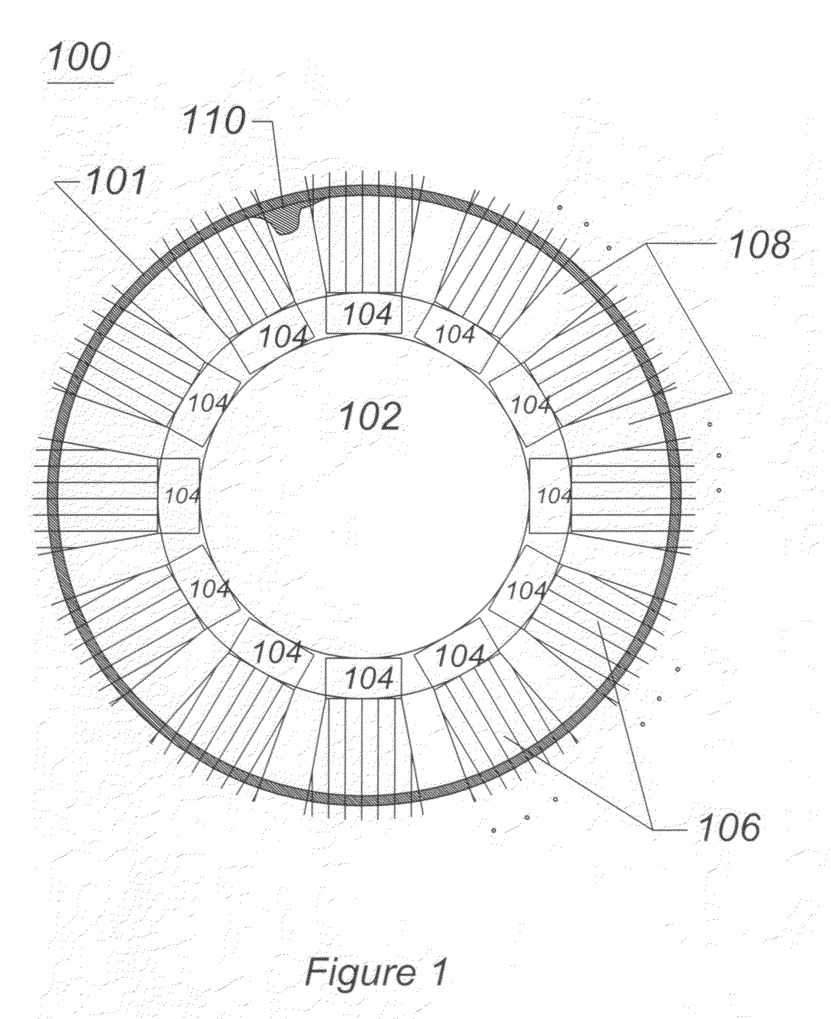
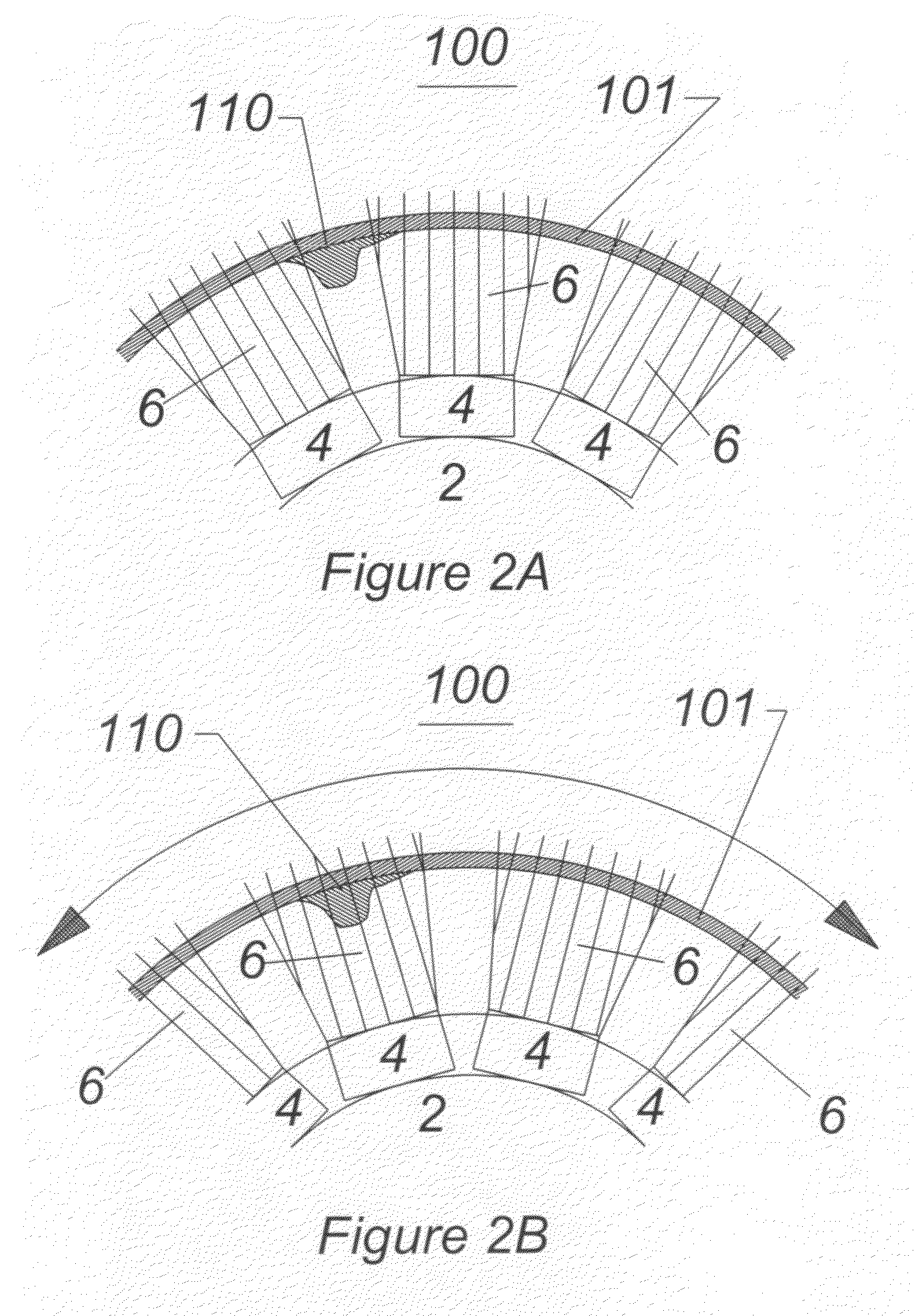
[0049]The invention herein described is an ultrasound imaging and treatment catheter comprising a rotationally vibrating array of ultrasound transducers. An embodiment of the catheter allows the flexibility and cost effectiveness of a conventional stationary ultrasound-imaging catheter but has superior image data gathering capabilities as is illustrated in FIGS. 1, 2A, and 2B.

[0050]FIG. 1 illustrates, in cross section, a distal tip of a stationary imaging catheter 102 imaging a body lumen 100. The body lumen 100 has an inside surface irregularity 110 on a body lumen wall 101. The imaging catheter 102 comprises a plurality or array of ultrasound transducers 104, a plurality of fields of view or imaging areas 106 and a plurality of blind spots or blind areas 108. Examples of body lumens include arteries, veins, ureters, the bladder, the urethra and biliary ducts. The transducers 104 are placed circumferentially around the tip 102. Each transducer 104 transmits ultrasound energy and re...


PUM


Abstract

A rotationally vibrating imaging catheter and method of utilization has an array of ultrasound or optical transducers and an actuator along with signal processing, display, and power subsystems. The actuator of the preferred embodiment is a solid-state nitinol actuator. The actuator causes the array to oscillate such that the tip of the catheter is rotated through an angle equal to or less than 360 degrees. The tip is then capable of rotating back the same amount. This action is repeated until the desired imaging information is acquired. The rotationally vibrating catheter produces more imaging points than a non-rotating imaging catheter and eliminates areas of missing information in the reconstructed image.Rotationally vibrating catheters offer higher image resolution than stationary array catheters and greater flexibility and lower costs than mechanically rotating imaging catheters.The rotationally vibrating array carried on a catheter is vibrated or rocked forward and backward to allow for acquisition of three-dimensional information within a region around the transducer array.The addition of adjunctive therapies to the imaging catheter enhances the utility of the instrument. Examples of such therapies include atherectomy, stent placement, thrombectomy, embolic device placement, and irradiation.

Description

PRIORITY CLAIM[0001]This application is a continuation of U.S. patent application Ser. No. 10 / 440,742, now U.S. Pat. No. 7,524,289, which is a continuation-in-part of U.S. patent application Ser. No. 09 / 690,795, filed on Oct. 17, 2000, now, U.S. Pat. No. 6,592,526, which is a continuation-in-part of U.S. patent application Ser. No. 09 / 632,617, filed on Aug. 4, 2000, now abandoned, which is a continuation-in-part of U.S. patent application Ser. No. 09 / 236,936, filed on Jan. 25, 1999, now U.S. Pat. No. 6,110,121 the entirety of which are hereby incorporated herein by reference.FIELD OF INVENTION[0002]This invention relates to improvements in devices for intravascular ultrasound (IVUS) and optically guided catheter systems.BACKGROUND OF INVENTION[0003]Intravascular ultrasound is a rapidly evolving imaging technique most commonly employed in coronary and iliofemoral arteries. The technique has the potential to facilitate the study of aneurysm progression, atherosclerosis or dissection a...

Claims


Application Information

Patent Timeline
Patent Type & Authority Applications(United States)
IPC IPC(8): A61B8/14A61B17/32A61B18/18A61M29/00A61B8/12
CPCA61B8/12A61B8/445A61B8/0808A61B8/4461
Inventor LENKER, JAY A.
Owner LENKER JAY A
Why Eureka
Try Eureka