Submerged Geo-Ocean Thermal Energy System

Inactive Publication Date: 2009-09-03
LOCKHEED MARTIN CORP
View PDF8 Cites 65 Cited by
  • Summary
  • Abstract
  • Description
  • Claims
  • Application Information

AI Technical Summary

Benefits of technology

[0012]The second heat exchanger comprises a cold zone whose temperature is regulated by the fact that it is thermally coupled to a deep-water layer. Preferably, the deep-water layer exhibits a high heat capacity and a temperature that is substantially constant regardless of latitude, weather conditions, the annual solar cycle, or even the daily solar cycle. The thermoelectric system interposes the first heat exchanger and the second heat exchanger.
[0013]In some embodiments, the hot zone of the first heat

Problems solved by technology

There are several problems with conventional geothermal systems that have thus far limited their use.
First, the hot gas from the geothermal source is highly corrosive.
As a result, the lifetime of the turbine and other system components can be compromised.
Second, atmospheric temperature acts as the heat sink for conventional geothermal systems.
To further exacerbate matters, the reduction in power generation capacity tends to occur at times when such power is needed most (e.g., wh

Method used


Image

  • Submerged Geo-Ocean Thermal Energy System
  • Submerged Geo-Ocean Thermal Energy System
  • Submerged Geo-Ocean Thermal Energy System

Examples


Embodiment Construction

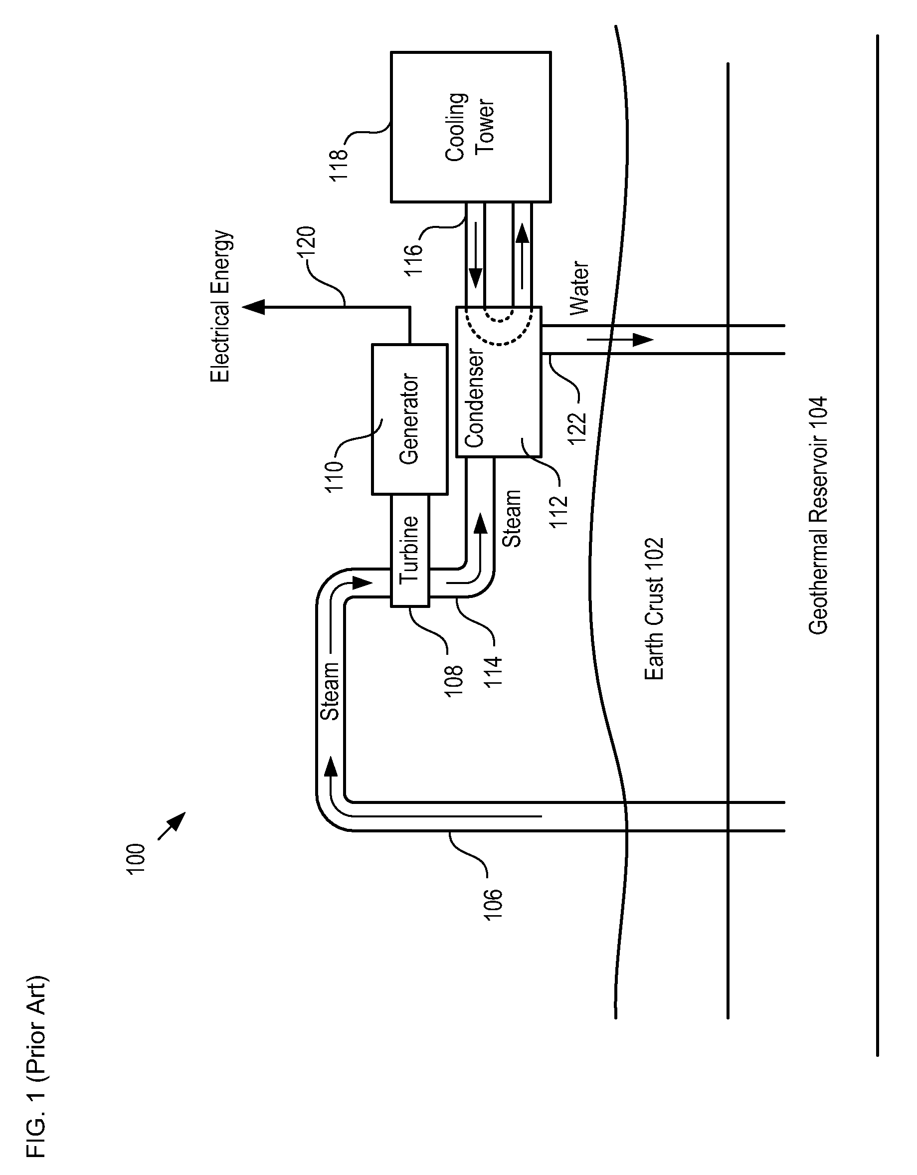
[0024]FIG. 1 depicts a schematic diagram of details of a prior-art dry steam geothermal energy conversion system. Energy system 100 comprises inlet conduit 106, turbine 108, generator 110, condenser 112, conduits 114 and 116, cooling tower 118, and outflow conduit 122. Turbine 108 and generator 110 collectively define a turbogenerator. In cases, a water pump is coupled to the outflow of condenser 112 to drive the return water to greater depths or to facilitate flow in a very long or narrow outflow conduit 122.

[0025]Inlet conduit 106 is inserted through earth crust 102 into geothermal reservoir 104. Inlet conduit 106 conveys steam from geothermal reservoir 104 to turbine 108. Turbine 108 is operatively coupled to generator 110.

[0026]The steam from geothermal reservoir 104 drive turbine 108, which turns generator 110 to produce electrical energy. The generated electrical energy is conveyed to an end user or storage facility on output cable 120.

[0027]Conduit 114 receives the steam that...


PUM


Abstract

A system for generating electrical energy using a naturally occurring temperature difference is disclosed. The system provides electrical energy by thermally conduit a geothermal heat source and cold deep-level water to opposing sides of a thermoelectric element. The thermoelectric element generates electrical energy based on the temperature difference between these two surfaces.

Description

CROSS REFERENCE TO RELATED APPLICATIONS[0001]This case claims priority to: U.S. Provisional Patent Application Ser. No. 61 / 033,415, filed Mar. 3, 2008 (Attorney Docket: 711-136US); and U.S. Provisional Patent Application Ser. No. 61 / 042,185, filed Apr. 3, 2008 (Attorney Docket: 711-189US); each of which is incorporated herein by reference.[0002]If there are any contradictions or inconsistencies in language between this application and one or more of the cases that have been incorporated by reference that might affect the interpretation of the claims in this case, the claims in this case should be interpreted to be consistent with the language in this case.FIELD OF THE INVENTION[0003]The present invention relates to energy systems in general, and, more particularly, to geothermal energy systems.BACKGROUND OF THE INVENTION[0004]Non-petroleum-based energy sources are desirable. Geothermal and Ocean Thermal Energy Conversion (OTEC) systems represent two attractive such sources. Each can...

Claims


Application Information

Patent Timeline
IPC IPC(8): F03G7/04
CPCE21B41/0085F03G7/04Y02E10/10
Inventor RAPP, JOHN W.HOWARD, ROBERT JAMESNAGURNY, NICHOLAS J.
Owner LOCKHEED MARTIN CORP
Why Eureka
Try Eureka