Friction stirring-welding method

a friction stir welding and stirring technology, applied in the direction of soldering apparatus, manufacturing tools, welding devices, etc., can solve the problems of cavity flaw generation, significantly different deformation resistance, and unfavorable outward appearance, so as to prevent the reduction of welding strength, and facilitate the removal

Inactive Publication Date: 2009-09-03
HITACHI LTD
View PDF15 Cites 12 Cited by
  • Summary
  • Abstract
  • Description
  • Claims
  • Application Information

AI Technical Summary

Benefits of technology

[0009]The invention with respect to the first mechanism of welding obtains favorable results by the use of a welding tool having a small diameter projected part at a tip end of a large diameter shoulder. Desirably, the projected part has a smooth curved surface like a semispherical shape, if possible. Since the projected part can raise pressure in a region of plastic flow, the action of activating welding boundary surfaces increases. For an increase in pressure of plastic flow, it is also effective to provide a semispherical recess around the semispherical projected part to make these regularities contribute to an increase in contact area of the welding tool and a welding member. Also, it is desirable to round an outer peripheral surface of a tip end of the shoulder. Furthermore, since the use of a welding tool having a tip end of a certain radius of curvature also enables an increase in pressure of plastic flow, the action of activating welding boundary surfaces increases. When the action of activating welding boundary surfaces increases, a welding area increases and the welding strength increases.
[0012]When lapped surfaces of welding members are coated with soft metal, surface oxide films on welding boundary surfaces can be made easy to remove. In the case where welding members are made of carbon steel, such method is very effective. Nickel, zinc, and copper are especially effective as soft metal.
[0013]By providing a trapezoidal member on a surface of that member, into which a welding tool is pressed, or working the member to make the same trapezoidal in shape, it is possible to prevent reduction in welding strength even when an indentation is produced due to pressing of the welding tool.
[0014]Also, a distance between a welding tool and lapped surfaces can be made short by performing welding in a state wherein a groove is provided on a lapped surface of one of members, and a projected part is provided on a lapped surface of the other of the members, the projected part being fitted into the groove. This method is suited to the case where thick plates are to be welded together.
[0017]With the friction stir welding method by means of a welding tool according to the invention, it is possible to positively generate plastic flow on welding boundary surfaces of a lap joint to remove and discharge a surface oxide film to activate the boundary surfaces. Thereby, welding with a high welding strength becomes possible. Also, welding of different metals is enabled.

Problems solved by technology

In the case where welding tools are pressed into both of an upper plate and a lower plate in lap welding by means of friction stir welding, there is caused an unfavorable problem in terms of outward appearance that a large hole is formed in a welded part to reach the lower plate.
Also, in case of lap welding of materials, such as aluminum and nickel, which are considerably different in melting point from each other, there is caused a problem that the both are considerably different in deformation resistance from each other and cavity flaw is generated, since aluminum has the melting point of 660° C. while nickel has the melting point of 1455° C., and welding tools are pressed into both metals of aluminum and nickel.

Method used


Image

  • Friction stirring-welding method
  • Friction stirring-welding method
  • Friction stirring-welding method

Examples


first embodiment

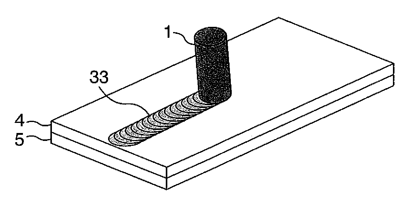
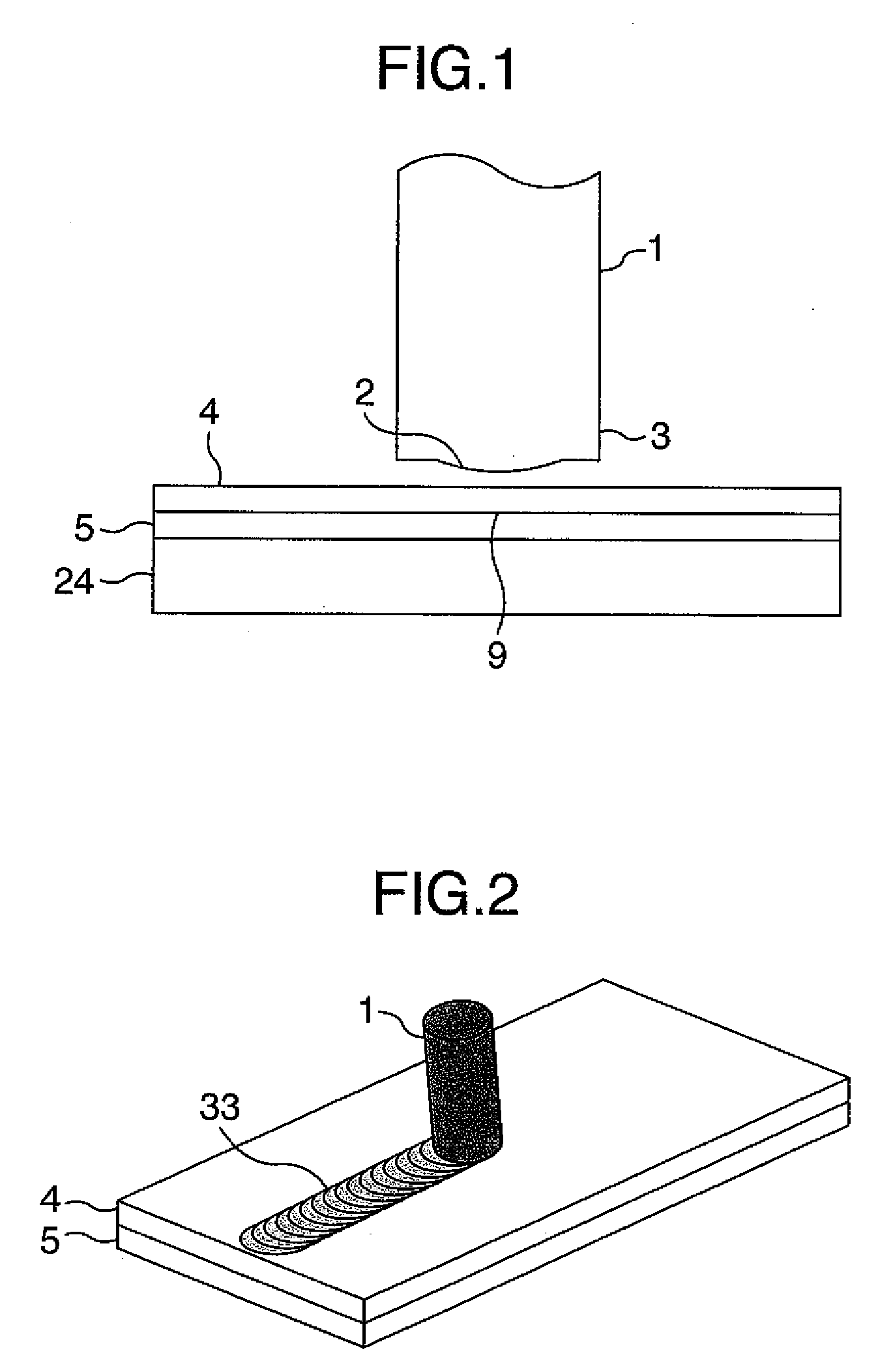
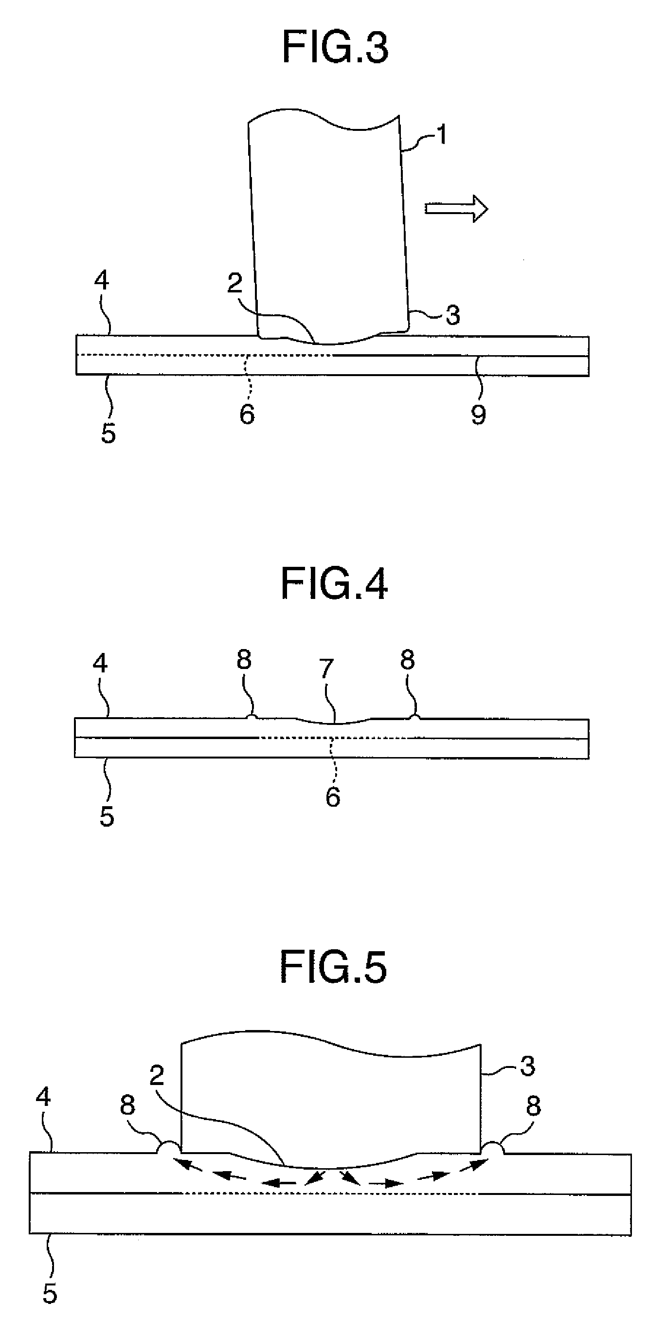
[0038]FIG. 1 is a cross sectional view showing a first embodiment. A welding tool 1 comprises a small diameter projected part 2 at the tip end of a large diameter shoulder 3. A welding test piece comprises an upper plate 4 and a lower plate 5, which lap each other and are arranged on a bearing member 24. FIG. 2 is a perspective view in the course of welding. By rotating and moving the welding tool 1 in a direction of welding in a state, in which it is pressed only into the upper plate 4 from a side of the upper plate 4, welding boundary surfaces 6 of the upper plate 4 and the lower plate 5 can be welded to each other. An indentation 7 is produced on the upper plate 4 as the welding tool 1 is moved. FIG. 3 is a cross sectional view showing a direction of welding in the course of welding. An axis of rotation of the welding tool 1 in the course of welding is inclined on an opposite side to a direction of welding indicated by an arrow, that is, a backward angle side. FIG. 4 is a cross s...

second embodiment

[0047]FIG. 11 is a cross sectional view showing a state before welding in a second embodiment. The embodiment differs from the first embodiment in that a trapezoidal member 30 is provided on a welding part of an upper plate 4 to make the upper plate 4 thick. FIG. 12 is a cross sectional view showing the welded part in the second embodiment. While an indentation 7 is produced on the welded part, any indentation does not remain and a flat surface is obtained when the welded part is ground flat.

third embodiment

[0048]FIG. 13 is a cross sectional view showing a state before welding in a third embodiment. FIG. 14 is a cross sectional view showing a welded part. The embodiment differs from the first embodiment in that a groove 32 is provided on an upper plate 4 and a projected part 31 is provided on a lower plate 5 to be fitted into the groove. Thereby, since the welding part can be made smaller in thickness than the upper plate 4, it is possible to perform welding for a further large plate thickness.


PUM

PropertyMeasurementUnit
melting pointaaaaaaaaaa
thicknessaaaaaaaaaa

Abstract

A friction stirring-welding method capable of increasing the welding strength of a lap joint. A welding tool (1) comprises a small diameter projected part (2) at the tip of a shoulder (3). The welding tool is press-fitted to the upper plate (4) of the lap joint while being rotated. By a friction stirring action, an upper plate side welding boundary surface (6) plastically flows, a surface oxidation film on a lapped surface is peeled off, and the boundary surface is activated to provide an excellent welding part. Also, since the welding tool is formed in a shape having the small diameter semispherical projected part (2) at the tip thereof, the thickness (12) of an upper plate welding part is increased, and a lap joint part with high welding strength can be provided.

Description

[0001]This application is a Continuation application of application Ser. No. 10 / 560,225, filed Dec. 12, 2005, the contents of which are incorporated herein by reference in their entirety. Prior application Ser. No. 10 / 560,225 is a National Stage application filed under 35 USC 371 of International Application No. PCT / JP04 / 008580, filed Jun. 11, 2004.FIELD OF THE INVENTION[0002]The present invention relates to a friction stir welding method and a friction stir welding apparatus.DESCRIPTION OF RELATED ART[0003]A conventional technology for welding of a lap joint by means of the friction stir welding technique includes a method of using a welding tool having a flat-shaped tip end surface, or a welding tool having a recess on a tip end surface, and pressing the welding tool into one of members to cause friction stir on the one of the members to make use of plastic flow produced thereby to weld the same to the other of the members (see, for example, JP-A-2001-314 981)[0004]In welding of a...

Claims


Application Information

Patent Timeline
Patent Type & Authority Applications(United States)
IPC IPC(8): B29C65/06B23K20/12
CPCB23K20/1265B23K20/1255
Inventor AOTA, KINYAINAGAKI, MASAHISAHIRANO, SATOSHIOKAMOTO, KAZUTAKA
Owner HITACHI LTD
Why Eureka
Try Eureka