Live Bottom Hole Pressure for Perforation/Fracturing Operations

a pressure measurement and perforation technology, applied in the direction of borehole/well accessories, instruments, survey, etc., can solve the problems of insufficient accuracy of pressure at the surface, less than optimal fracturing of the hydrocarbon bearing formation, and a less productive well, so as to improve the treatment efficiency and optimize the reservoir.

a pressure measurement and perforation technology, applied in the direction of borehole/well accessories, instruments, survey, etc., can solve the problems of insufficient accuracy of pressure at the surface, less than optimal fracturing of the hydrocarbon bearing formation, and a less productive well, so as to improve the treatment efficiency and optimize the reservoir.

US20090218094A1Active Publication Date: 2009-09-03SCHLUMBERGER TECH CORP

Image

  • Live Bottom Hole Pressure for Perforation/Fracturing Operations
  • Live Bottom Hole Pressure for Perforation/Fracturing Operations
  • Live Bottom Hole Pressure for Perforation/Fracturing Operations

Examples


Embodiment Construction

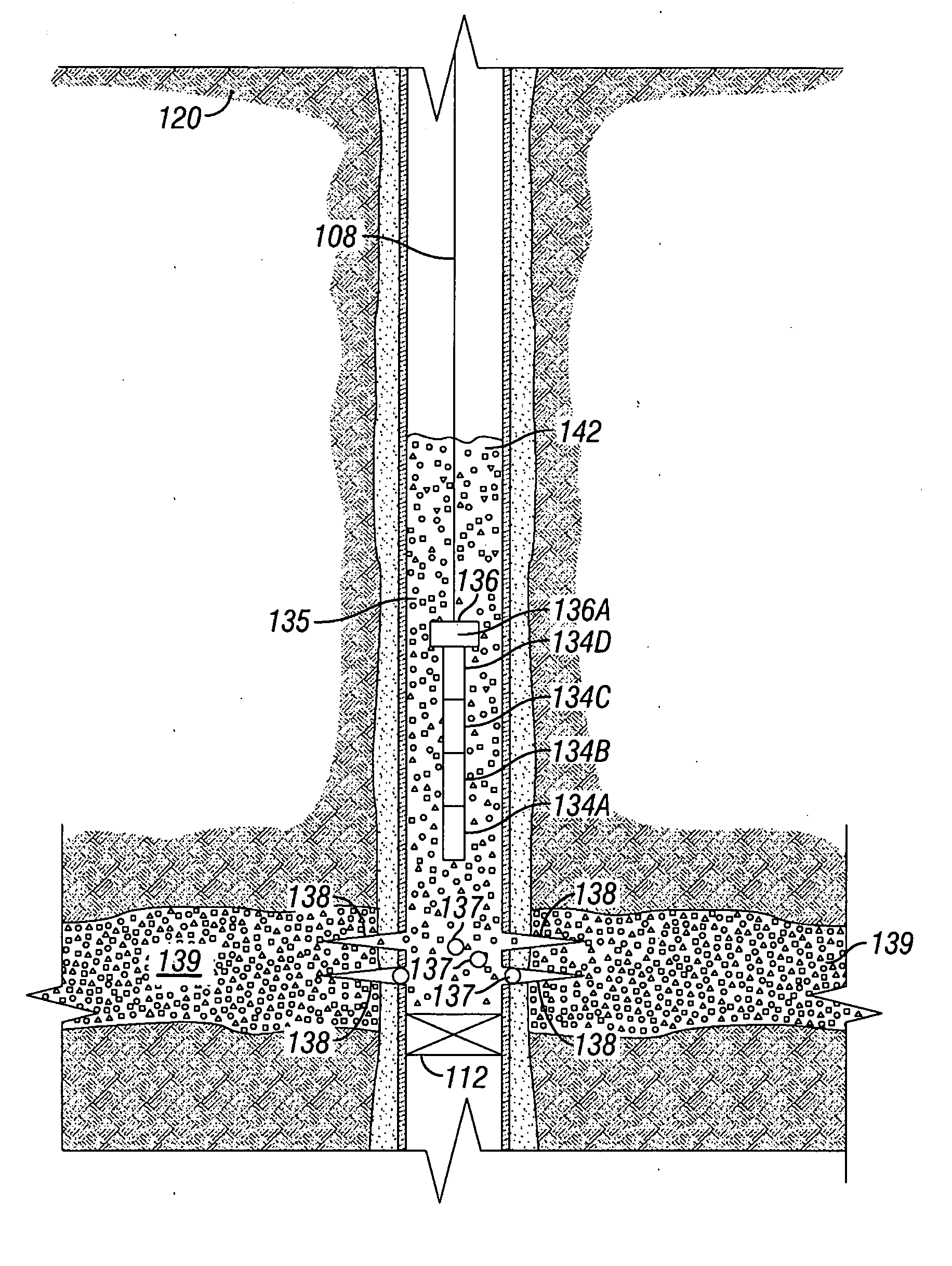
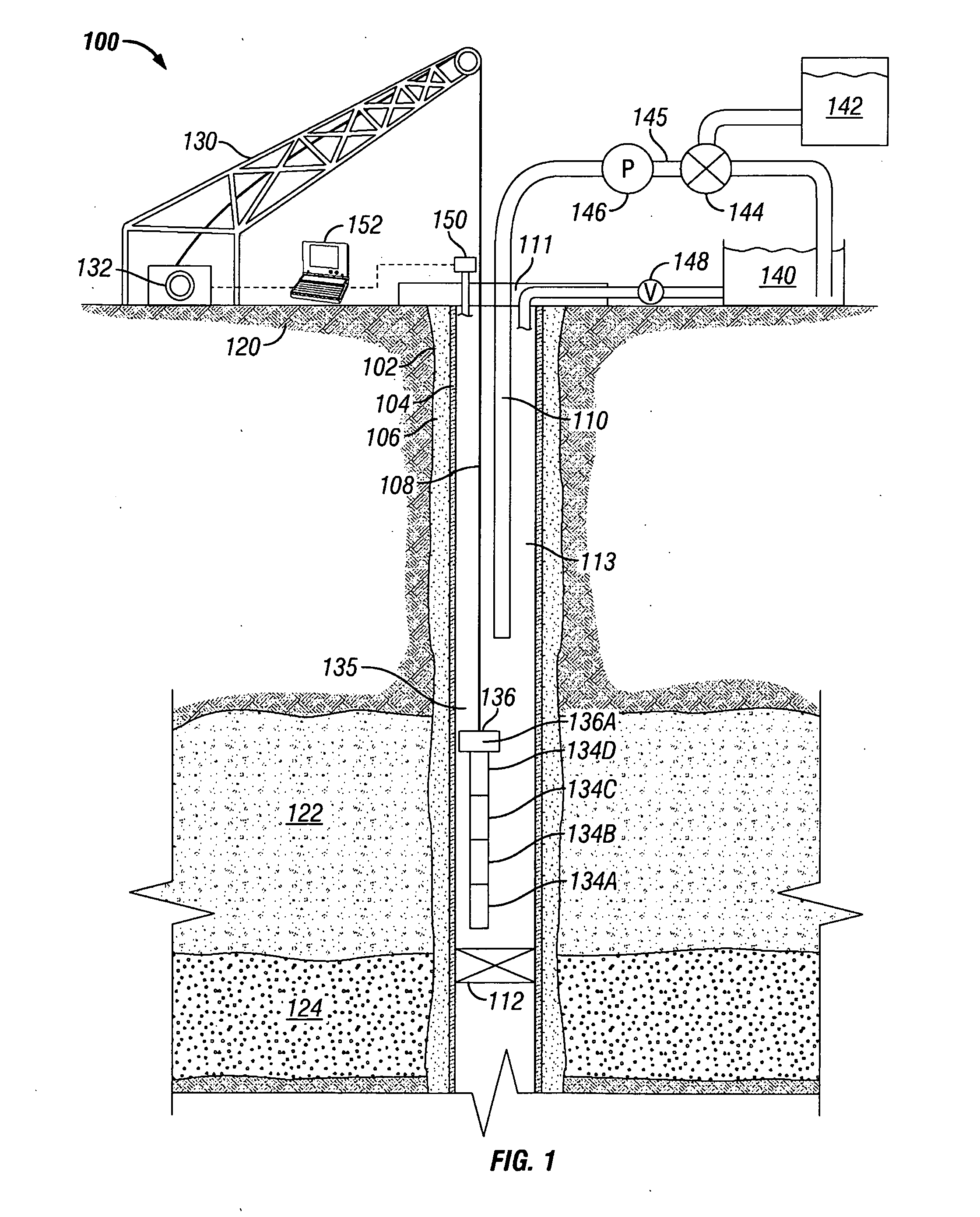
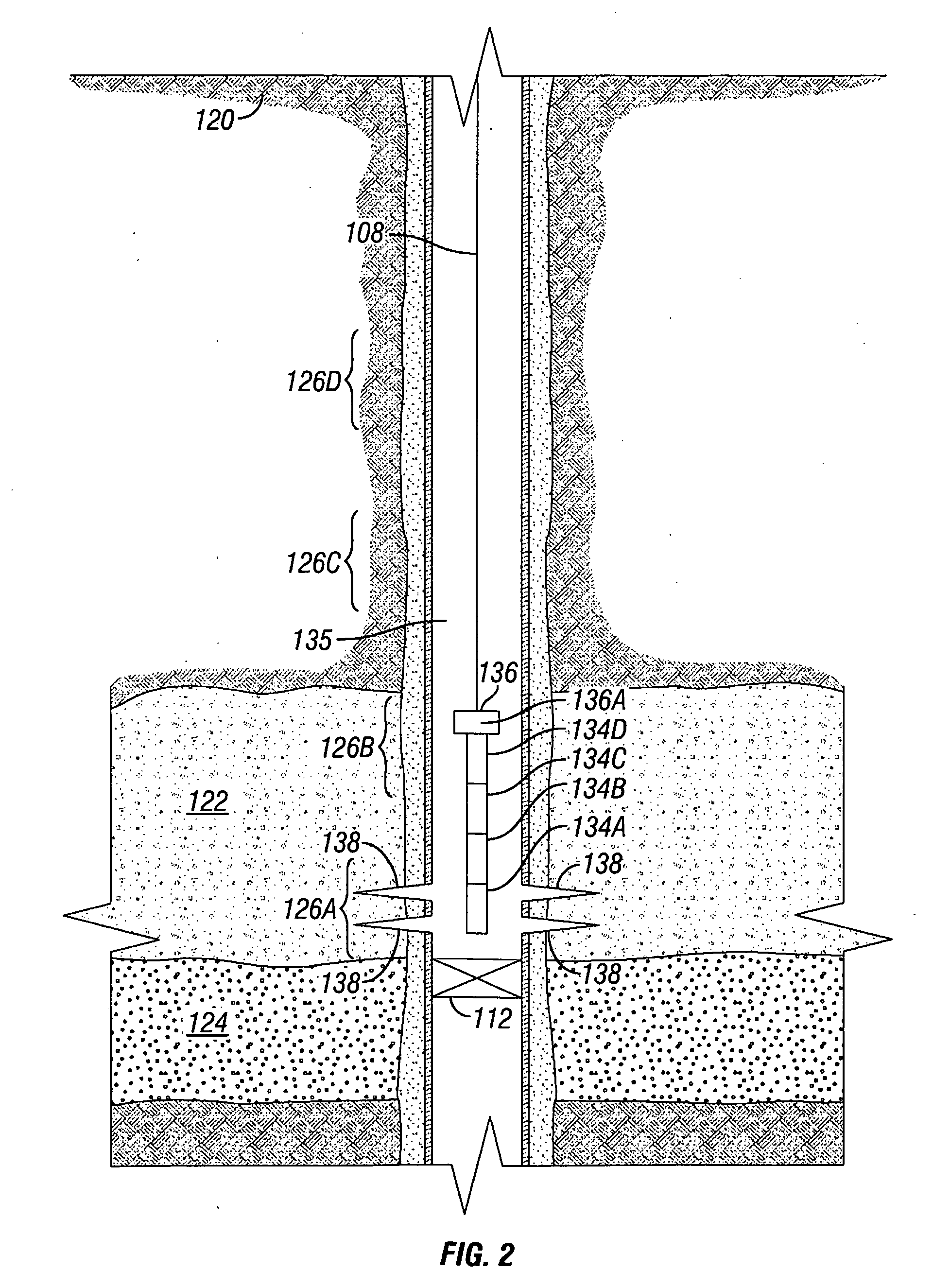
[0022]In the following detailed description, reference is made to the accompanying drawings that show, by way of illustration, specific embodiments in which the invention may be practiced. These embodiments are described in sufficient detail to enable those skilled in the art to practice the invention. It is to be understood that the various embodiments of the invention, although different, are not necessarily mutually exclusive. For example, a particular feature, structure, or characteristic described herein in connection with one embodiment may be implemented within other embodiments without departing from the spirit and scope of the invention. In addition, it is to be understood that the location or arrangement of individual elements within each disclosed embodiment may be modified without departing from the spirit and scope of the invention. The following detailed description is, therefore, not to be taken in a limiting sense, and the scope of the present invention is defined on...


PUM


Abstract

A method of determining when to stop pumping proppant during hydraulic fracturing in a wellbore is described. By accurately detecting tip screen-out with a bottom hole pressure gauge mounted to a perforating gun, the optimal amount of proppant can be supplied to a fracture while avoiding the risks associated with wellbore screen-out.

Description

TECHNICAL FIELD[0001]The present invention relates generally to pressure measurement in a wellbore. More specifically, the invention relates to real time pressure measurement in a wellbore during fracturing operations to better detect screen-out.BACKGROUND OF THE INVENTION[0002]The statements in this section merely provide background information related to the present disclosure and may not constitute prior art.[0003]Hydraulic fracturing is a process whereby a subterranean hydrocarbon reservoir is stimulated to induce a highly conductive path to the formation, increasing the flow of hydrocarbons from the reservoir. A fracturing fluid is pumped at high pressure to crack the formation, creating larger passageways for hydrocarbon flow. The fracturing fluid may include a proppant, such as sand or other solids that fill the cracks in the formation, so that, when the fracturing treatment is done and the high pressure is released, the fracture remains open.[0004]Key to a successful fractur...

Claims


Application Information

Patent Timeline
03 Sep 2009
Publication
US20090218094A1
IPC
E21B43/26; E21B49/00; E21B47/06; G05D7/06
CPC
E21B47/06; E21B43/26
Inventors
MCLEOD, TREVOR; MAHDI, ABBAS