Deionization apparatus and method of manufacturing the same

a deionization apparatus and deionization technology, applied in the direction of electrostatic separation, crystal growth process, solid separation, etc., can solve the problems of uneconomic method using ion exchange resin, partially blocked pores of carbon material, electrical conductivity may deteriorate, etc., to prevent the pores of electrodes from being blocked, improve ion removal efficiency, and prevent a reduction of electrical conductivity

Inactive Publication Date: 2009-09-03
SAMSUNG ELECTRONICS CO LTD
View PDF10 Cites 41 Cited by
  • Summary
  • Abstract
  • Description
  • Claims
  • Application Information

AI Technical Summary

Benefits of technology

[0015]It is an aspect of the invention to provide a capacitive deionization apparatus capable of reducing contact resistance between a carbon material and a collector in the manufacture of electrodes to improve electrical conductivity and capable of preventing pores of the carbon material from being partially clogged.
[0016]It is another aspect of the invention to provide a capacitive deionization apparatus capable of maintaining a uniform spacing distance between the stacked collectors, thereby improving ion removal efficiency.
[0017]Further, it is another aspect of the invention to provide a capacitive deionization apparatus having collectors capable of reducing the manufacturing costs and preventing damage.

Problems solved by technology

However, the method using ion exchange resin is uneconomical in that an acid or base solution should be used in the regeneration of resin and a large amount of polymer resin and chemicals should be used to process a large amount of water.
Accordingly, the pores of the carbon material may be partially clogged and electrical conductivity may deteriorate due to contact resistance.
Further, since each layer is sealed using a gasket made of rubber or Teflon, when a number of cells are stacked and fastened to each other, upper, middle and lower cells cannot be fastened with a uniform force.
In this case, the manufacturing cost increases.
If other metals are used to reduce the manufacturing cost, the metals may be corroded.
Further, in a case of using an inexpensive carbon foil, since the boundary of the collector is exposed to the outside in the structure disposed in the patent, there is a problem that the collector may be damaged.

Method used


Image

  • Deionization apparatus and method of manufacturing the same
  • Deionization apparatus and method of manufacturing the same
  • Deionization apparatus and method of manufacturing the same

Examples


Embodiment Construction

[0052]Reference will now be made in detail to exemplary embodiments of the present invention, examples of which are illustrated in the accompanying drawings, wherein like reference numerals refer to like elements throughout. The embodiments are described below to explain the present invention by referring to the figures.

[0053]Hereinafter, a capacitive deionization apparatus according to an embodiment of the present invention will be described in detail with reference to the accompanying drawings.

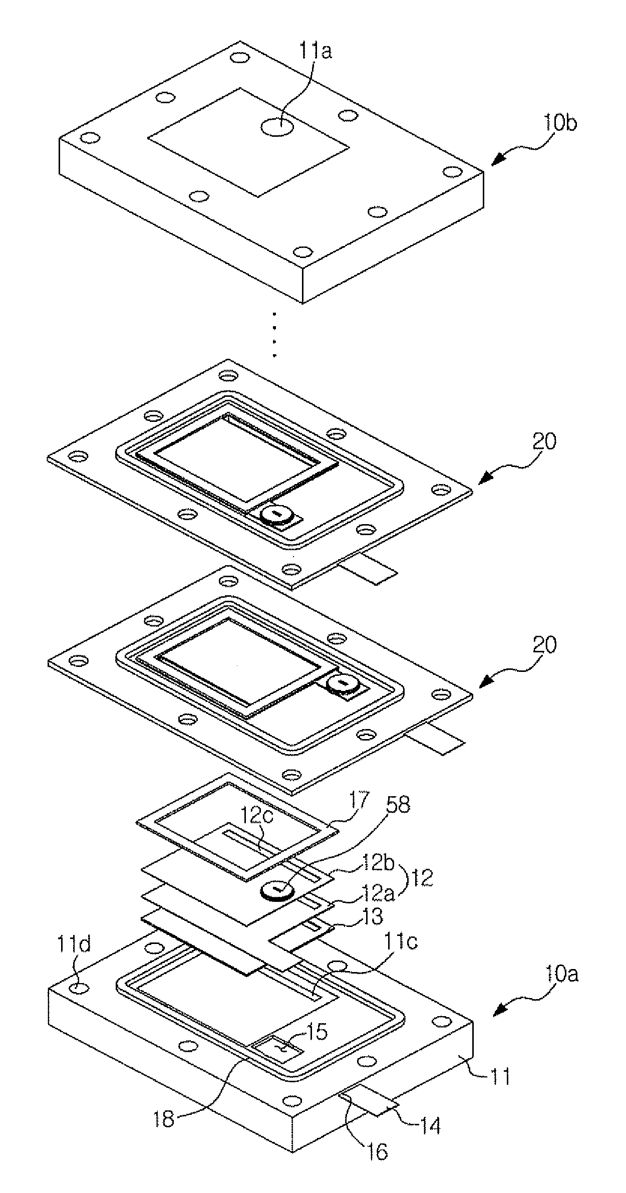
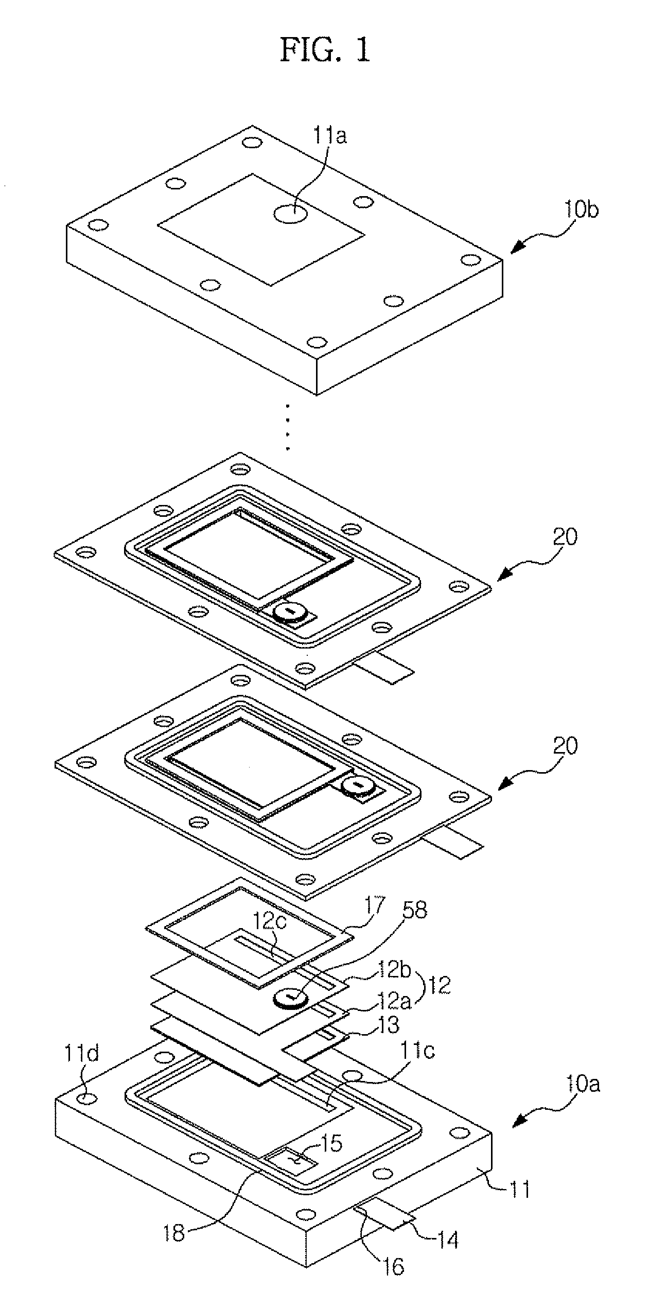
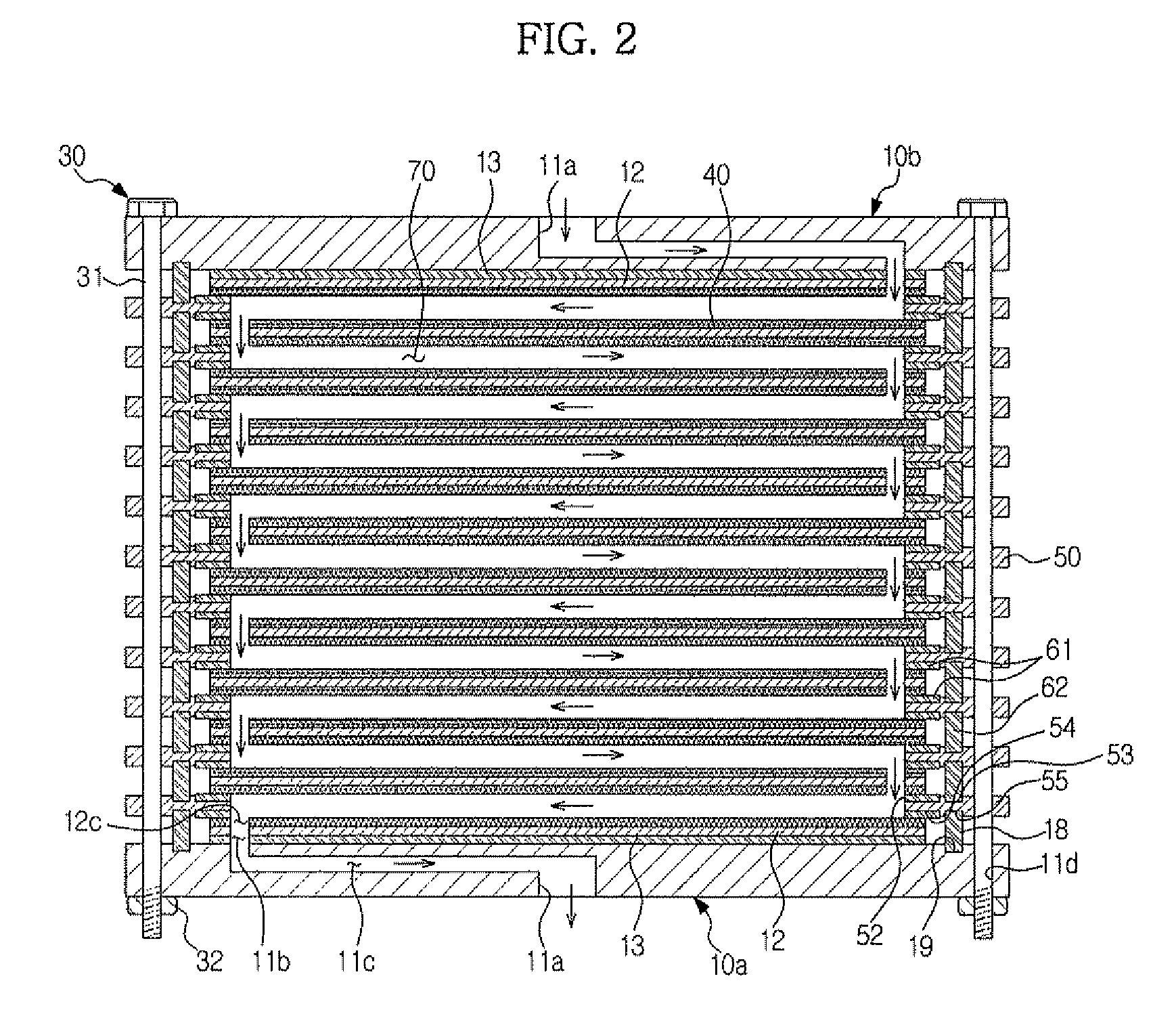
[0054]FIG. 1 illustrates an exploded perspective view of the capacitive deionization apparatus according to the embodiment of the present invention. FIG. 2 illustrates a cross-sectional view of the capacitive deionization apparatus according to the embodiment of the present invention. FIG. 3 illustrates an exploded perspective view of a spacer unit included in the capacitive deionization apparatus according to the embodiment of the present invention.

[0055]The capacitive deionization apparatu...


PUM

PropertyMeasurementUnit
sizeaaaaaaaaaa
specific distanceaaaaaaaaaa
flowing timeaaaaaaaaaa

Abstract

A capacitive deionization apparatus, wherein a spacing distance between electrodes of cells is uniformly maintained and a flow in the cells is optimized to improve efficiency of the deionization apparatus and contact resistance between a carbon material and a collector is reduce to improve electrical conductivity, is disclosed. The capacitive deionization apparatus which includes a plurality of electrode modules, each having a collector and electrodes disposed on upper and lower surfaces of the collector to electrically and chemically remove ions from liquid, includes a plurality of plates made of a stiff material are alternately stacked with the electrode modules such that the electrode modules are spaced at specific intervals, wherein the collector and the electrodes are pressed by a pair of adjacent plates among the plurality of plates to maintain a contact therebetween.

Description

CROSS-REFERENCE TO RELATED APPLICATION[0001]This application claims the benefit of Korean Patent Application No. 2008-0018781, filed on Feb. 29, 2008 in the Korean Intellectual Property Office, the disclosure of which is incorporated herein by reference.BACKGROUND OF THE INVENTION[0002]1. Field of the Invention[0003]The present invention relates to an ion removing apparatus capable of removing ions from the liquid, and, more particularly, to a capacitive deionization (CDI) apparatus capable of removing ion components from the liquid using electrical and chemical methods.[0004]2. Description of the Related Art[0005]Among various methods used to purify water containing salt components or heavy metals, a method using ion exchange resin is widely used. However, the method using ion exchange resin is uneconomical in that an acid or base solution should be used in the regeneration of resin and a large amount of polymer resin and chemicals should be used to process a large amount of water....

Claims


Application Information

Patent Timeline
Patent Type & Authority Applications(United States)
IPC IPC(8): B03C5/02
CPCC02F1/4691C02F5/00C02F2301/024C02F2201/46145C02F2201/002C02F1/4693C02F1/46
Inventor NOH, HYONG SOOPARK, DAO WOOKNOJIMA, HIDEOCHANG, PHIL SOO
Owner SAMSUNG ELECTRONICS CO LTD
Why Eureka
Try Eureka