
Wastewater Treatment Method and System

Inactive Publication Date: 2009-09-03
CLEARFLEAU
View PDF6 Cites 14 Cited by
  • Summary
  • Abstract
  • Description
  • Claims
  • Application Information

AI Technical Summary

Benefits of technology

[0016]Advantageously, the anaerobic step may be performed more efficiently, due to being performed in a dedicated receptacle. Also, in being performed at the same time as one or both of steps b) and c), the method can make a more efficient use of time by performing two steps at the same time.
[0026]The part-treated mix produced in step (a) may have reduced dissolved BOD, nitrogen and phosphorus.

Problems solved by technology

However, SBRs have the disadvantage that it is not possible to provide a truly anaerobic environment, and therefore phosphate removal from the wastewater is not as effective.
Disadvantages common to both systems include the time required for settling and the need for disinfection of the effluent where the effluent is put to use, for example in irrigation, rather than mere disposal.
However, the use of membrane filters as described in these patents can be problematic.
The filters described force effluent through the filters at relatively high pressure (60 psi) which fouls the membranes in a manner making them difficult to clean, due to physical properties of biosolids residue.

Method used


Image

  • Wastewater Treatment Method and System
  • Wastewater Treatment Method and System
  • Wastewater Treatment Method and System

Examples


first embodiment

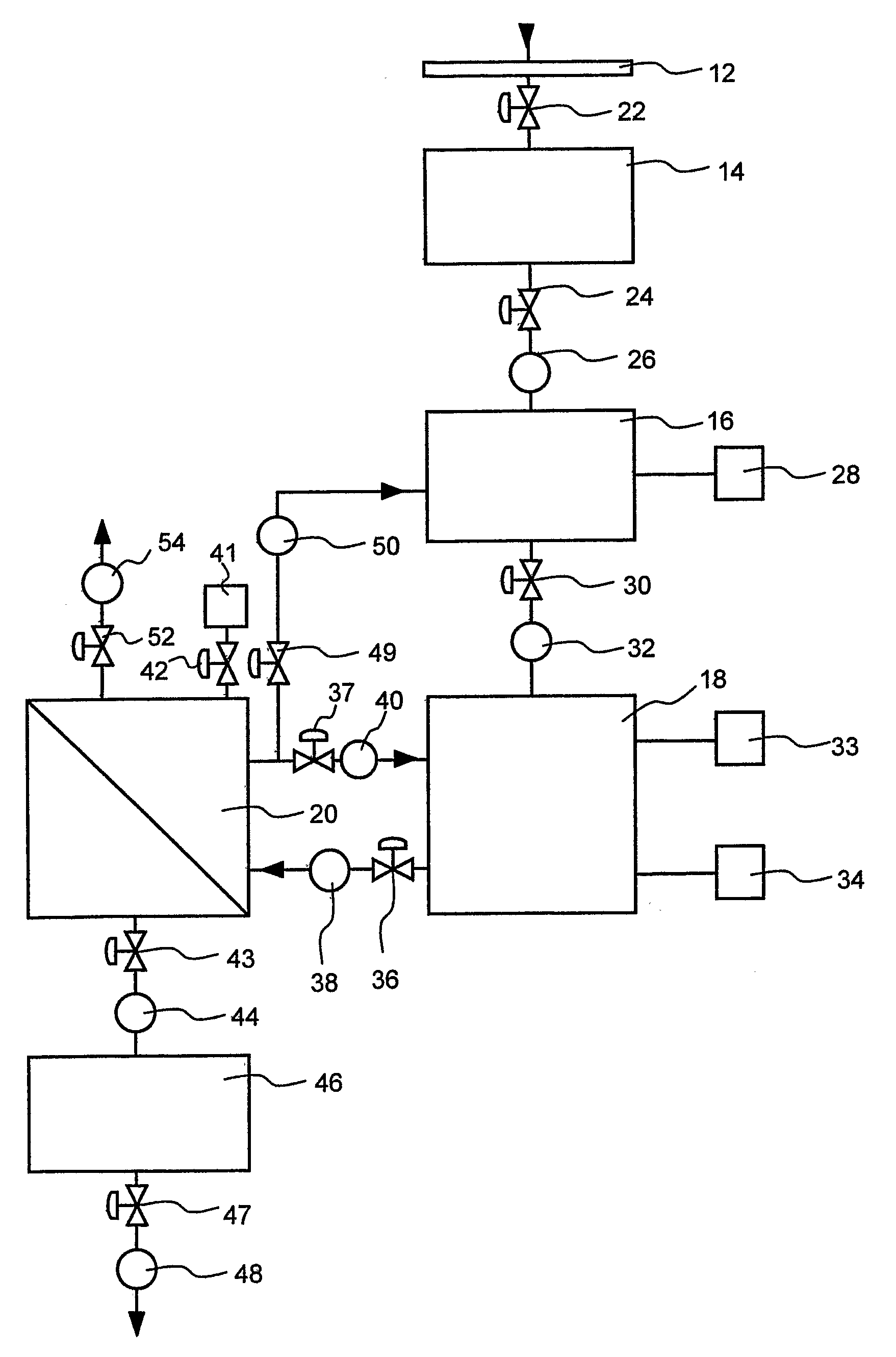
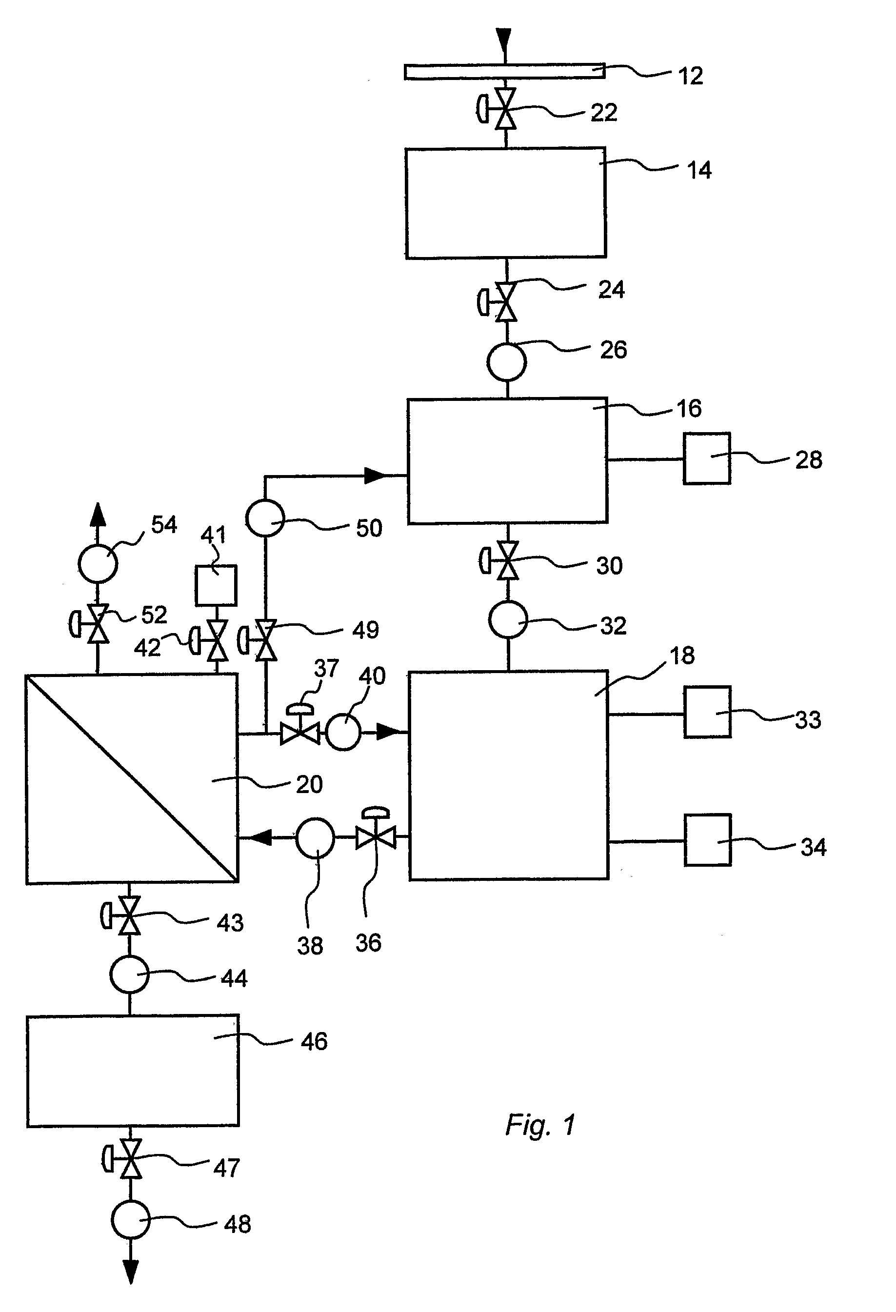
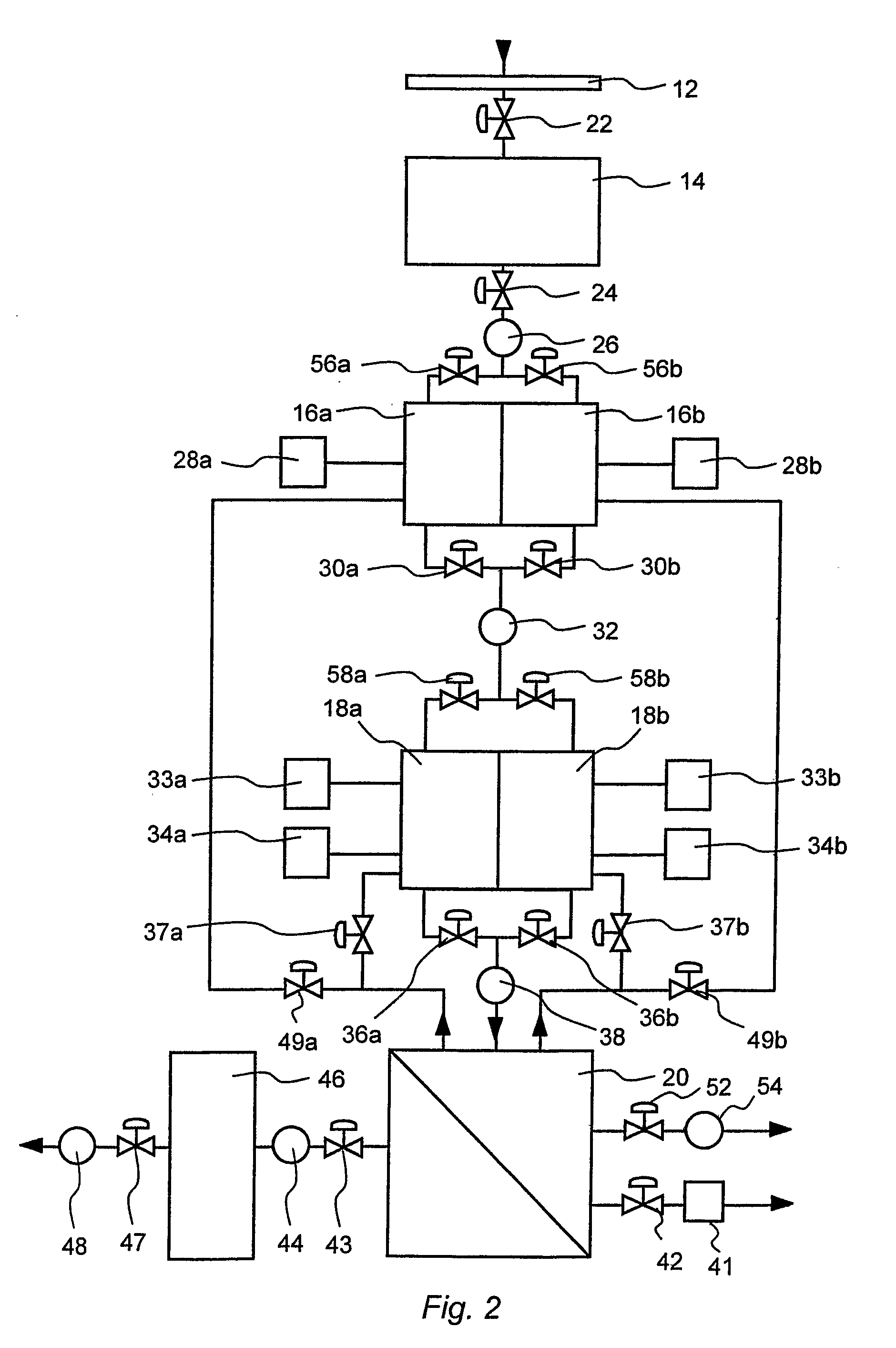
[0093]FIG. 2 illustrates another embodiment of the present invention, where like reference numerals denote like parts. This embodiment employs the use of two anaerobic tanks 16a,b and two SBR tanks 18a,b, and associated pumps valves and mixers. Additional anaerobic tank inlet diverter valves 56a,b and SBR tank inlet diverter valves 58a,b are required in this embodiment to ensure separation of flow of waste streams between the two anaerobic tanks 16a,b and two SBR tanks 18a,b. In this embodiment, a primary 8-hour cycle stream is performed via anaerobic tank 16a and SBR tank 18a, and a secondary 8 hour cycle stream is performed via anaerobic tank 16b and SBR tank 18b. The primary and secondary cycle streams run practically identically to each other and follow the same preliminary anaerobic contact, SBR and filtration phases as described above with respect to the first embodiment, however they run 4 hours out of phase with each another. In this way only one filtration unit 20 is requir...

second embodiment

[0094]Under the above time periods, the anaerobic tank 16, or 16a,b stores at least some liquid for about 5.5 to 6.0 hours, including introducing mixed liquor to the tank 16, or 16a,b prior to the preliminary anaerobic contact phase, the preliminary anaerobic contact phase, and the first to part of the fourth SBR phases. That is, the anaerobic tank 16, or 16a,b stores at least some liquid for more than half of each cycle. For this reason, two anaerobic tanks are required in the above-described As will be understood, the above time periods can be altered depending on the type of waste stream, the volume of each portion of anaerobically treated wastewater introduced into the SBR tank 18, or 18a,b, and the quality requirements of the output filtrate. In another embodiment, therefore, one anaerobic tank and two SBR tanks, and associated pumps valves and mixers, are used. In this embodiment, a primary 8 hour cycle stream is performed via the one anaerobic tank and a first one of the SBR...


PUM

PropertyMeasurementUnit
Volumeaaaaaaaaaa

Abstract

A method for treating wastewater is disclosed. In step a), a predetermined volume of the wastewater is mixed in a first receptacle with a predetermined volume of sludge-containing returned denitrified mixed liquor under anaerobic conditions for a predetermined time period to produce an anaerobically mix rich in released phosphates. In step b), at least a portion of the anaerobically treated mix is then treated in a second receptacle under aerobic and anoxic conditions to produce a part-treated mix. In step c) at least a portion of solids from the part-treated mix to produce a low reduced-solids effluent. Steps b) and c) are sequential and cyclical and the treatment in step a) occurs during one or both of steps b) and c). In an alternative method, a predetermined volume of wastewater is treated under aerobic and anoxic conditions to produce a part-treated mix. The predetermined volume of wastewater is treated in two or more distinct portions, and a predetermined time period elapses between the introduction of each of the portions. In this method, carbon present in one or more of a second or subsequent said distinct portion(s) is available for use in treatment under said anoxic conditions during step a).

Description

TECHNICAL FIELD[0001]The present invention relates to wastewater treatment systems and methods, and in particular to bioreactors for the removal of organic contaminants, nutrients and suspended solids from wastewater.BACKGROUND ART[0002]Bioreactors for the treatment of wastewater, such as municipal sewage, livestock wastewater and industrial wastewater, are well known. Bioreactors use several stages of treatment of the wastewater to remove or reduce nutrients such as phosphorus (poly-phosphates), nitrogen (eg. ammonia, nitrites, nitrates and total inorganic nitrogen (TIN)), biochemical oxygen demand (BOD), chemical oxygen demand (COD) and total suspended solids (TSS).[0003]A conventional activated sludge bioreactor process for nutrient removal is preceded by coarse screening followed by primary sedimentation or fine screening using a 2 mm screen. Effluent from the primary clarifier or the fine screen is then mixed with a mixed-liquor sludge and the resultant mix is treated anaerobic...

Claims


Application Information

Patent Timeline
IPC IPC(8): C02F3/30C02F3/12C02F3/28
CPCC02F3/1263C02F3/308C02F3/286C02F3/1268Y02W10/10C02F3/30C02F9/00
Inventor JOSSE, JUAN
Owner CLEARFLEAU
Learn More