Spot welding method, method for judging shape of nugget, spot welding machine and spot welding electrode

a technology of spot welding and nuggets, which is applied in the direction of electrode features, ohmic resistance heating, manufacturing tools, etc., can solve the problems of not being able to perform not being able to directly evaluate spot welding quality for an object, and not being able to achieve spot inspection through a spot check in the production line. , to achieve the effect of reducing production costs, reducing labor intensity and reducing labor intensity

Inactive Publication Date: 2009-09-03
DAIHATSU MOTOR CO LTD +1
View PDF14 Cites 25 Cited by
  • Summary
  • Abstract
  • Description
  • Claims
  • Application Information

AI Technical Summary

Benefits of technology

[0013]According to the present invention, spot welding quality is judged based on the configuration of a welding trace formed on the surface of a metal body in correspondence with a recess at the center of the electrode surface of the welding electrode, so it is possible to judge spot welding quality through non-destructive inspection. Further, it is possible to judge spot welding quality more easily with simpler equipment and with higher reliability.
[0014]Further, according to the present invention, in the process in which spot welding is performed by using a welding electrode having a recess of a predetermined depth at the electrode surface center, a judgment as to whether a nugget has been properly formed is made based on the resistance value at the time of welding, and further, a spot welding completion judgment is made. Therefore, it is possible to control spot welding quality in the spot welding process. As a result, the control of a production process using spot welding is facilitated, and it is possible to reduce generation of problems in spot welding such as defective welding.

Problems solved by technology

However, with chisel inspection, it is impossible to directly evaluate spot welding quality for an object that has not undergone destructive measurement.
However, a portion where a high tensile steel material has been spot-welded is harder than a portion where an ordinary steel plate has been welded, so it is not suited for chisel inspection through a spot check in the production line.
In this regard, no technique has been available which allows judgment of spot welding quality in the spot welding process.

Method used


Image

  • Spot welding method, method for judging shape of nugget, spot welding machine and spot welding electrode
  • Spot welding method, method for judging shape of nugget, spot welding machine and spot welding electrode
  • Spot welding method, method for judging shape of nugget, spot welding machine and spot welding electrode

Examples


Embodiment Construction

[0015]First, a spot welding method and a spot welding electrode according to an embodiment of the present invention will be described with reference to the drawings.

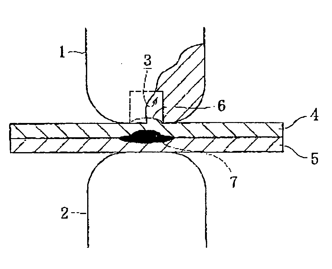
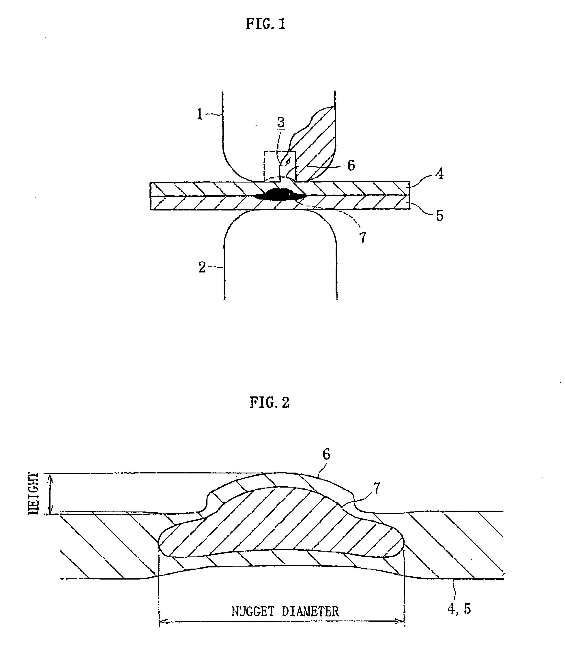
[0016]As shown in FIG. 1, of a pair of electrodes 1, 2 for performing spot welding, one electrode 1 has a recess 3 in an electrode surface. When spot welding is performed by using those electrodes, there is formed, as shown in FIGS. 1, 2, a convex welding trace 6 on a surface of steel plates 4, 5 (metal body) in correspondence with the recess 3 formed in the electrode surface of the electrode 1. Focusing attention on the convex welding trace 6, the inventors of the present invention examined the correlation between the height of the convex welding trace 6, the diameter of a nugget 7 (nugget diameter), and tensile shear strength (TSS).

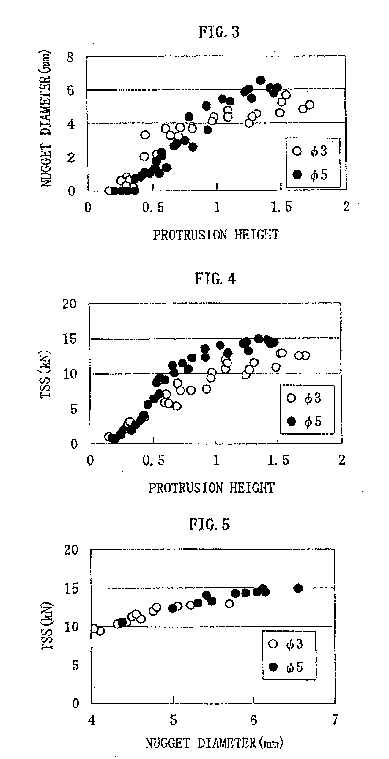
[0017]FIG. 3 shows an example of data showing the correlation between the height of the convex portion and the nugget diameter, FIG. 4 shows an example of data showing the correlation betwee...


PUM

PropertyMeasurementUnit
diameteraaaaaaaaaa
diameteraaaaaaaaaa
frequencyaaaaaaaaaa

Abstract

An electrode whose electrode surface is a substantially convex curved surface and which has at a center portion a recess set at a predetermined depth allowing a welding trace formed on a metal body surface to reach a deepest portion when a nugget is formed in a satisfactory manner by the spot welding is used as at least an electrode for performing the spot welding. The spot welding quality is judged based on a shape of the welding trace formed on the metal body surface by the spot welding in correspondence with the recess.

Description

FIELD OF THE INVENTION[0001]The present invention relates to a spot welding method, a method of judging nugget formation, a spot welding machine, and a spot welding electrode.BACKGROUND OF THE INVENTION[0002]As is known in the art, in spot welding, the quality of spot welding is evaluated on the basis of a nugget diameter. As a specific evaluation method, there is conducted an individual destructive measurement, such as a so-called chisel inspection in which a chisel is press-fitted into a gap between two steel plates spot-welded together to separate the spot-welded portion, measuring the bonded zone including the heat-affected zone, or a cutting inspection in which the spot-welded portion is cut to directly measure the nugget diameter.[0003]As non-destructive measurement techniques related to spot welding, there have been proposed various techniques such as a technique utilizing ultrasonic waves (JP 62-119453 A and JP 04-265854 A), a technique utilizing vibration (JP 09-171007 A), ...

Claims


Application Information

Patent Timeline
Patent Type & Authority Applications(United States)
IPC IPC(8): B23K9/32B23K11/11B23K11/30
CPCB23K11/3009B23K11/258
Inventor ABE, HIROSHISHINMYOU, TAKASHIKIKUCHI, RYO
Owner DAIHATSU MOTOR CO LTD
Why Eureka
Try Eureka