Casting device, solution casting apparatus, and casting method

Inactive Publication Date: 2009-09-03
FUJIFILM CORP
View PDF3 Cites 12 Cited by
  • Summary
  • Abstract
  • Description
  • Claims
  • Application Information

AI Technical Summary

Benefits of technology

[0018]According to the present invention, the casting device includes the outer side seal plates for shielding air flowing from the side ends of the decompression chamber in the width direction, and the shift mechanism for shifting each of the outer side seal plates to a position corresponding to the side end of the casting bead in conjunction with change in the width of the casting bead. Therefore, even when the width of the casting bead is changed, it is possible to easily adjust the width of the opening of the decompression chamber during the operation of the casting device. Thus, according to the

Problems solved by technology

However, in the melt-extrusion method, it is difficult to adjust the film thickness with high accuracy, and further fine streaks (die lines) easily occur on a surface of the film.
Accordingly, it is difficult to produce a film having high quality as an optical functional film.
During the casting process, when the clearance between the support and the decompression chamber is changed, the following problems occur in some cases.
For example, in accordance with change in pressure inside the decompression chamber, a position of the support where the dope reaches is changed, and thereby thickness unevenness of the casting film occurs.
Accordingly,

Method used


Image

  • Casting device, solution casting apparatus, and casting method
  • Casting device, solution casting apparatus, and casting method
  • Casting device, solution casting apparatus, and casting method

Examples


Embodiment Construction

[0031]Hereinafter, preferred embodiments of the present invention are described in detail. However, the present invention is not limited thereto.

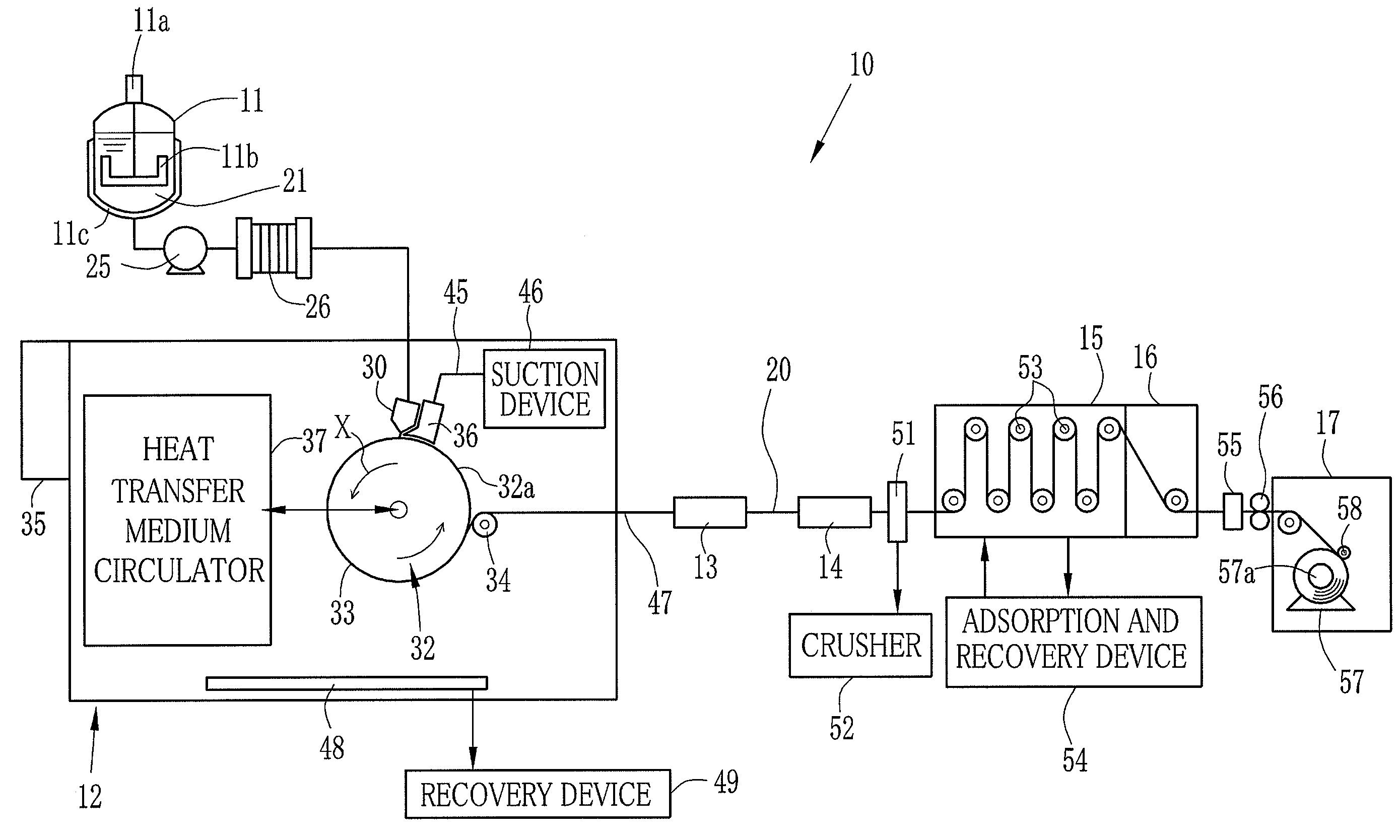
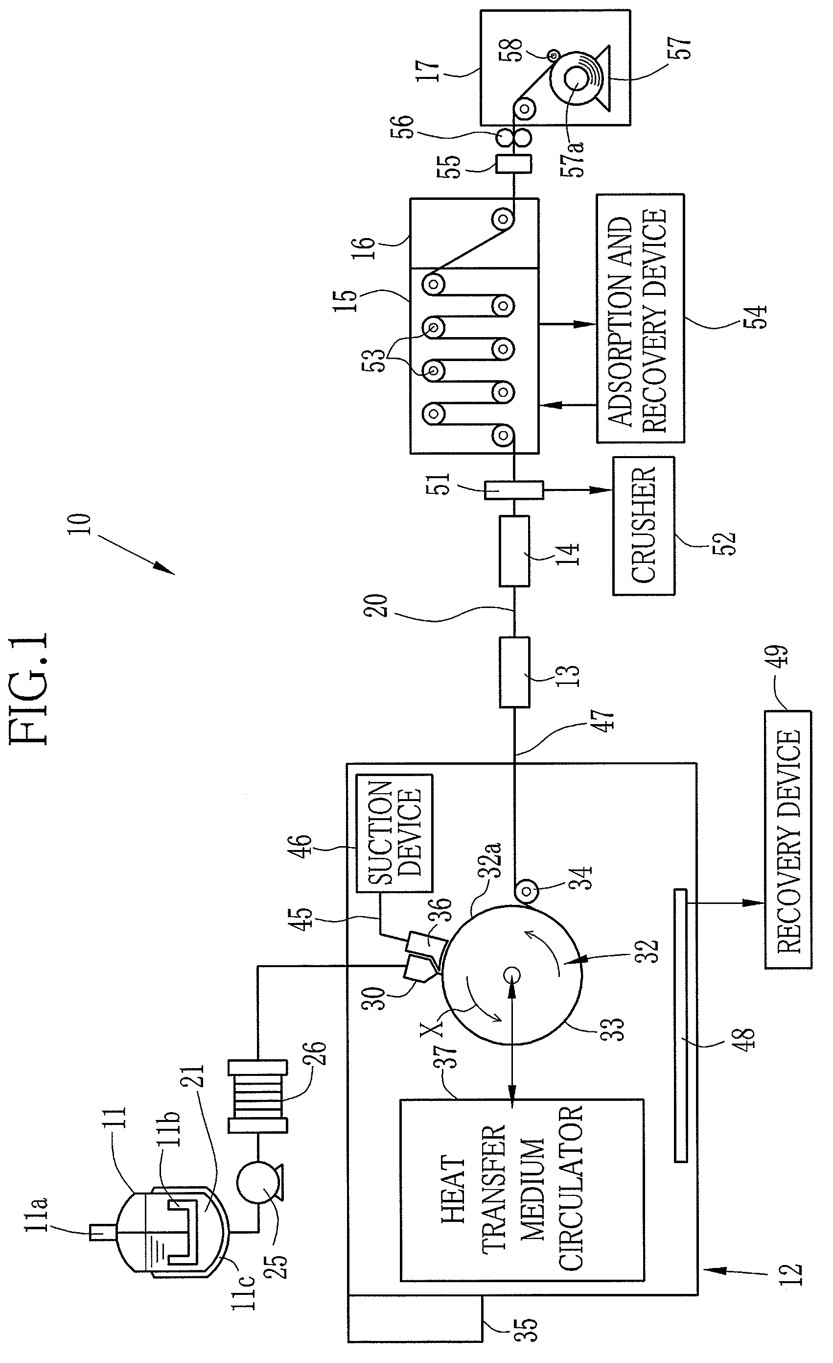
[0032]As shown in FIG. 1, a film production line 10 includes a stock tank 11, a casting chamber 12, a pin tenter 13, a clip tenter 14, a drying chamber 15, a cooling chamber 16, and a winding chamber 17.

[0033]The stock tank 11 is provided with a stirrer blade 11b rotated by a motor 11a and a jacket 11c. Inside the stock tank 11 is stored a dope 21 as a raw material for a film 20. A heat transfer medium flows inside the jacket 11c of the stock tank 11 such that a temperature of the dope 21 is adjusted to be within the range of 25° C. to 35° C. Since the stirrer blade 11b is rotated by the motor 11a in the stock tank 11, it is possible to keep the dope 21 in a constant state while preventing aggregation of a polymer and the like.

[0034]A pump 25 and a filtration device 26 are disposed in a downstream side from the stock tank 11. An adequate am...


PUM

PropertyMeasurementUnit
Widthaaaaaaaaaa
Areaaaaaaaaaaa

Abstract

A casting drum is rotated around a shaft. A peripheral surface of the casting drum moves in an X direction. A dope is discharged through a casting die onto the peripheral surface such that a casting bead is formed so as to extend from a discharge port of the casting die to the peripheral surface. A decompression chamber decompresses an upstream side from the casting bead in a moving direction of the casting drum. The decompression chamber is provided with a sensor unit for detecting a width of the casting bead in a Y direction as width data. A control section shifts outer side seal plates in the Y direction based on the width data detected by the sensor unit such that the outer side seal plates are located in an upstream side from side ends of the casting bead in the X direction. Upon formation of a casting bead having a new width, the control section shifts the outer side seal plates in the Y direction based on the width data of the casting bead having the new width such that the outer side seal plates are located in the upstream side from the side ends of the casting bead having the new width in the X direction.

Description

FIELD OF THE INVENTION[0001]The present invention relates to a casting device, a solution casting apparatus, and a casting method.BACKGROUND OF THE INVENTION[0002]A polymer film (hereinafter referred to as film) has advantages such as excellent light transmission properties and flexibility. Accordingly, the film is widely used as an optical functional film. As a representative of the film, a cellulose ester film using cellulose acylate or the like has excellent toughness, and phase difference is small in the cellulose ester film. Therefore, the cellulose ester film is utilized as a base of photosensitive material. Additionally, the cellulose ester film is utilized as a protective film in a polarizing filter and an optical compensation film as components of a liquid crystal display (LCD) whose market is increasingly expanded recently.[0003]As a film production method, mainly, there are a melt-extrusion method and a solution casting method. In the melt-extrusion method, a polymer is h...

Claims


Application Information

Patent Timeline
IPC IPC(8): B29D7/01B29C55/02B29C48/76
CPCB29C41/26B29C47/522B29K2001/00B29C48/465
Inventor OCHIAI, AKINORI
Owner FUJIFILM CORP
Why Eureka
Try Eureka