Motor drive control device and motor drive control system

a technology of control device and control system, which is applied in the direction of motor/generator/converter stopper, electronic commutator, dynamo-electric converter control, etc., can solve the problems of large substrate size on which the position detecting sensor is disposed, and increase the cost of the device, so as to reduce the cost, reduce the effect of torque ripple, and reduce the effect of torque fluctuation width

Inactive Publication Date: 2009-09-03
DAIKIN IND LTD
View PDF22 Cites 12 Cited by
  • Summary
  • Abstract
  • Description
  • Claims
  • Application Information

AI Technical Summary

Benefits of technology

[0039]The motor drive control device according to the first to fifth aspects of the invention performs control of the driving of the brushless motor by a configuration disposed with the two position detecting units, but the motor drive control device does not require a unique circuit or the like for drive control having a complicated algorithm and can control the driving of the brushless motor using a circuit or the like for drive control in a case where the device is disposed with three position detecting units. Consequently, a reduction in costs can be realized.
[0040]According to the motor drive control device according to the sixth and seventh aspects of the invention, in 60-degree energization, which is the phase of the three phases that outputs the least torque, the phase of the current to be outputted is the same phase as the induced voltage generated in that drive coil, so the minimum value of the torque output becomes higher in comparison to the case according to the third aspect of the present invention. Thus, the fluctuation width of the torque, that is, the torque ripple, can be made small.
[0041]According to the motor drive control device according to the eighth and ninth aspects of the invention, the same torque is obtained regardless of the direction of rotation of the brushless motor.
[0042]According to the motor drive control device pertaining to the tenth aspect of the invention, the motor drive control device becomes able to grasp the accurate position of the rotor.
[0043]According to the motor drive control device pertaining to the eleventh aspect of the invention, the drive signals can be changed even if the position detection signals do not change.
[0044]According to the motor drive control device pertaining to the twelfth and thirteenth aspects of the invention, the torque ripple is controlled, and noise and vibration can be controlled.

Problems solved by technology

However, costs become higher when there are many of these position detecting sensors, and the size of the substrate on which the position detecting sensors are disposed ends up becoming large.

Method used


Image

  • Motor drive control device and motor drive control system
  • Motor drive control device and motor drive control system
  • Motor drive control device and motor drive control system

Examples


embodiment

(1) Entirety and Configuration of Motor

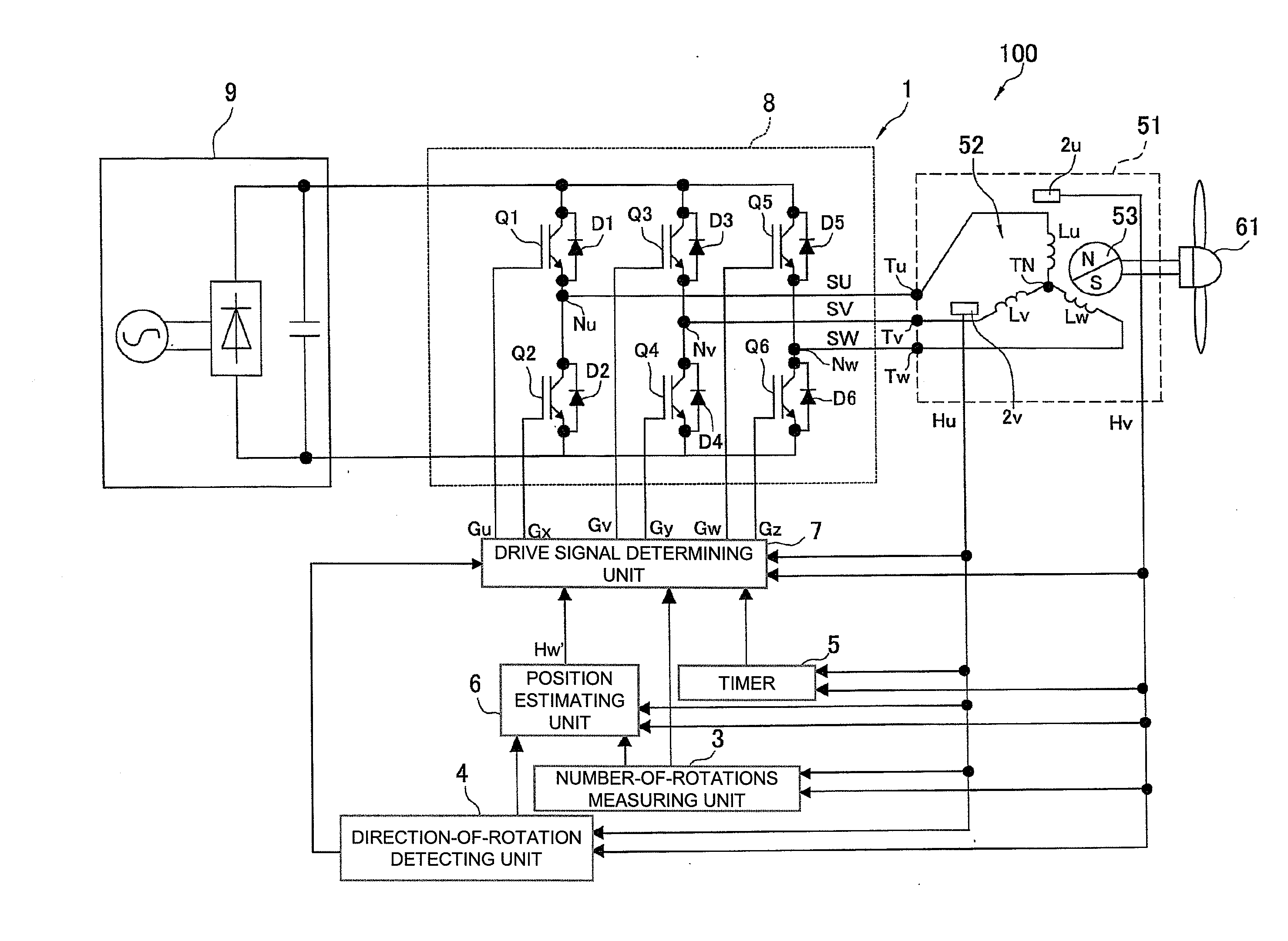
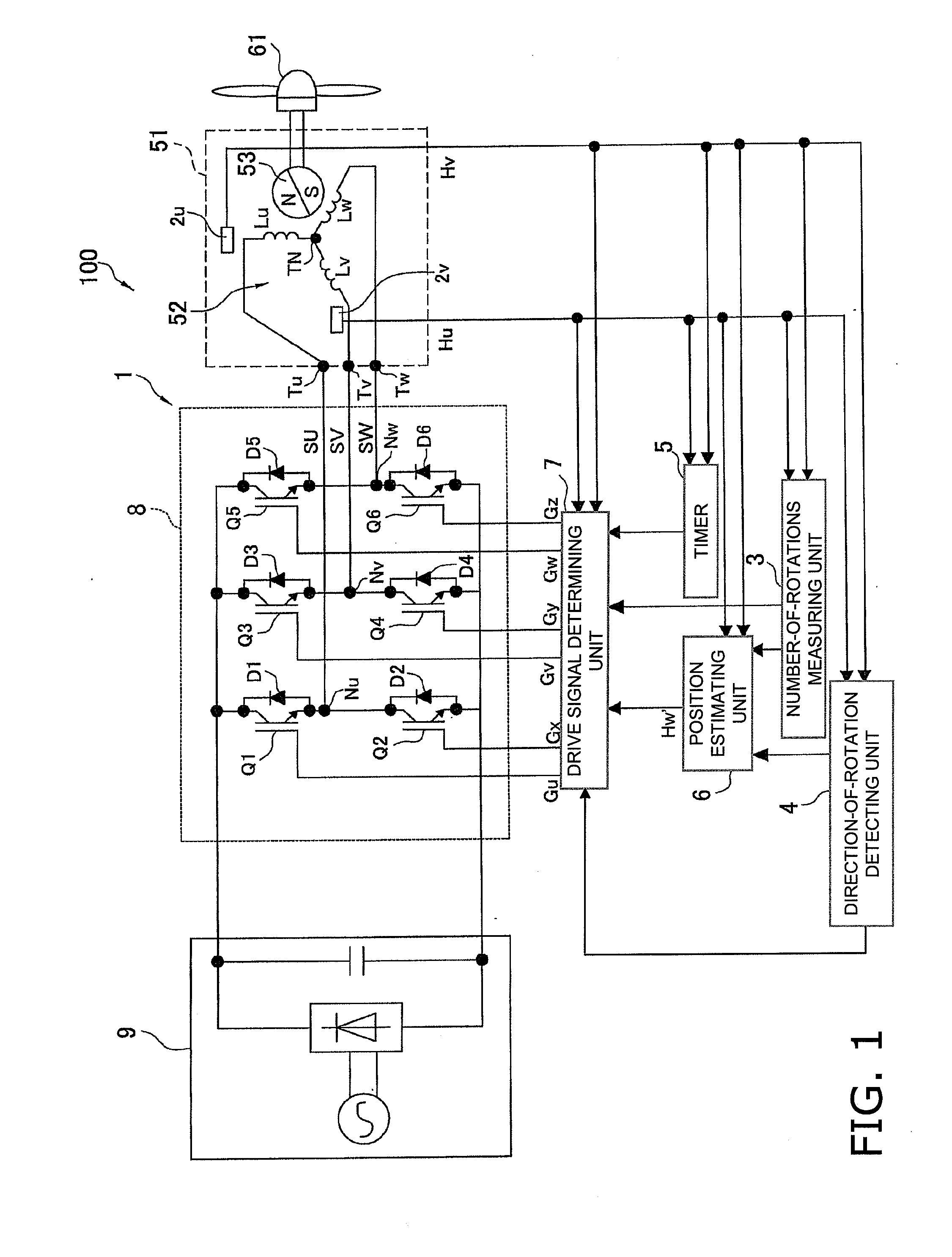
[0078]FIG. 1 is an overall configurable diagram of a motor drive control system 100 that includes a motor 51 and a motor drive control device 1 for controlling the driving of this motor. Here, examples of types of the motor generally include a direct current motor, an alternating current motor, a stepping motor and a brushless DC motor and the like, but in the present embodiment, a brushless DC motor is used.

[0079]The brushless DC motor 51 is, for example, a fan motor used in a fan 61 in an outdoor unit of an air conditioner, and the brushless DC motor 51 is disposed with a stator 52 and a rotor 53.

[0080]The stator 52 includes drive coils Lu, Lv and Lw of a U phase, a V phase and a W phase that are star-connected. One end of the drive coil Lu of the U phase is connected to a drive coil terminal TU of the U phase, one end of the drive coil Lv of the V phase is connected to a drive coil terminal TV of the V phase, one end of the drive coil Lw of ...


PUM


Abstract

A motor drive control device for controlling the driving of a brushless motor includes position detecting units (e.g. sensors or Hall elements), a drive signal determining unit and a drive signal outputting unit (an output circuit). The position detecting units are disposed in positions apart from each other by an electric angle of 120 degrees and output position detection signals representing the position of the rotor with respect to the stator. The drive signal determining unit determines drive signals for driving the 3-phase drive coils on the basis of the position detection signals. The drive signal outputting unit generates and outputs, to the 3-phase drive coils, the drive signals that have been determined by the drive signal determining unit.

Description

TECHNICAL FIELD[0001]The present invention relates to a motor drive control device and particularly to a motor drive control device that controls a driving of a brushless motor that includes a stator having 3-phase drive coils and a rotor having plural magnetic poles and to a motor drive control system that uses this motor drive control device.BACKGROUND ART[0002]In recent years, in air conditioners disposed with devices such as a compressor and a blowing fan, a 3-phase brushless DC motor, for example, has been used as a power source of these devices.[0003]Generally, a 3-phase brushless DC motor includes a rotor comprising a permanent magnet having plural magnetic poles and a stator having 3-phase drive coils. A current corresponding to the position of the rotor with respect to the stator is allowed to flow in the drive coils of this kind of brushless DC motor by a motor drive control device for controlling the driving of this motor. Thus, in the drive coils, a magnetic field corres...

Claims


Application Information

Patent Timeline
Patent Type & Authority Applications(United States)
IPC IPC(8): H02P6/16H02P6/06H02P6/08H02P6/14
CPCH02P6/165H02P6/14H02P1/16H02P6/17
Inventor SATO, TOSHIAKIHATAKEYAMA, TAKAYUKIITAGAKI, TETSUYASUGA, SHUNSUKE
Owner DAIKIN IND LTD
Why Eureka
Try Eureka