Charge loss compensation during programming of a memory device

a memory device and charge loss technology, applied in the field of memory devices, can solve problems such as single bit charge loss, intrinsic charge loss, and defects in data retention characteristics of floating gates

Active Publication Date: 2009-09-03
MICRON TECH INC
View PDF6 Cites 10 Cited by
  • Summary
  • Abstract
  • Description
  • Claims
  • Application Information

AI Technical Summary

Problems solved by technology

Immediately after programming, the floating gate can experience multiple forms of charge loss that occur at the time of ion implantation that can cause defects in the data retention characteristics of the floating gate.
These include single bit charge loss, intrinsic charge loss, and quick charge loss.
Single bit charge loss is the result of a defective memory cell that exhibits electron leakage.
This leakage can be accelerated with voltage or high temperature stress and results in inferior data retention.
The leakage of these electrons after programming then causes a one time shift in the threshold voltage.
Quick charge loss also causes an immediate Vt shift after a programming pulse.
When a cell passes the verify operation, the cell is inhibited from further programming and quick charge loss begins.
Additionally, the enlarged Vt distributions can overlap and result in errors in reading the different states.

Method used


Image

  • Charge loss compensation during programming of a memory device
  • Charge loss compensation during programming of a memory device
  • Charge loss compensation during programming of a memory device

Examples


Embodiment Construction

[0023]In the following detailed description of the invention, reference is made to the accompanying drawings that form a part hereof and in which is shown, by way of illustration, specific embodiments in which the invention may be practiced. In the drawings, like numerals describe substantially similar components throughout the several views. These embodiments are described in sufficient detail to enable those skilled in the art to practice the invention. Other embodiments may be utilized and structural, logical, and electrical changes may be made without departing from the scope of the present invention. The following detailed description is, therefore, not to be taken in a limiting sense, and the scope of the present invention is defined only by the appended claims and equivalents thereof.

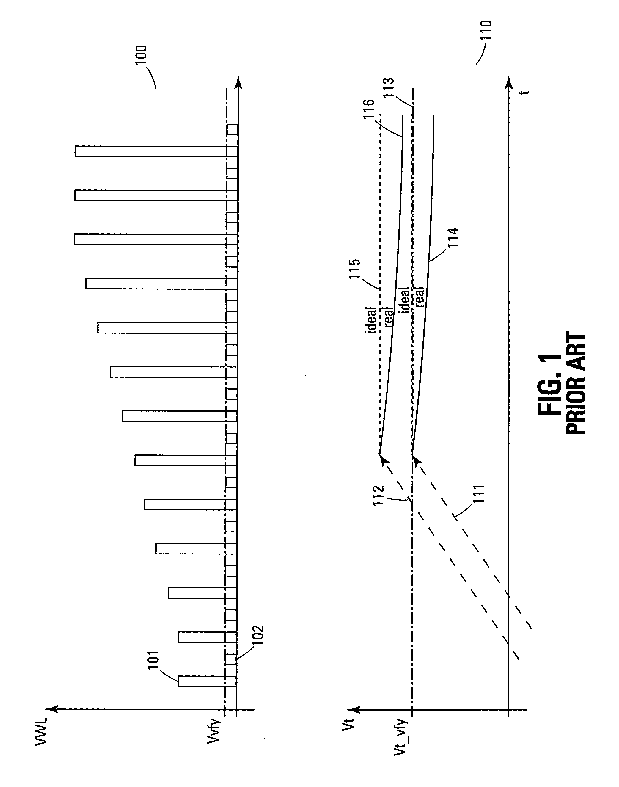
[0024]FIG. 3 illustrates a plot of a typical memory cell Vt versus time “t”. This plot shows the quick charge loss (QCL) that occurs in a typical floating gate, non-volatile memory device. This f...


PUM


Abstract

A selected memory cell on a selected word line is programmed through a plurality of programming pulses that are incremented by a step voltage. After a successful program verify operation, programming of the selected memory cell is inhibited while other memory cells of the selected word line are being programmed. Another program verify operation is performed on the selected memory cell. If the program verify operation fails, a bit line coupled to the selected cell is biased at the step voltage and a final programming pulse is issued to the selected word line. The selected memory cell is then locked from further programming without evaluating the final program verify operation.

Description

RELATED APPLICATION[0001]This application claims priority to Italian Patent Application Serial No. RM2008A000114, filed Feb. 29, 2008, entitled “CHARGE LOSS COMPENSATION DURING PROGRAMMING OF A MEMORY DEVICE,” which is commonly assigned.TECHNICAL FIELD OF THE INVENTION[0002]The present invention relates generally to memory devices and in particular the present invention relates to non-volatile memory devices.BACKGROUND OF THE INVENTION[0003]Memory devices are typically provided as internal, semiconductor, integrated circuits in computers or other electronic devices. There are many different types of memory including random-access memory (RAM), read only memory (ROM), dynamic random access memory (DRAM), static RAM (SRAM), synchronous dynamic RAM (SDRAM), and flash memory.[0004]Flash memory devices have developed into a popular source of non-volatile memory for a wide range of electronic applications. Flash memory devices typically use a one-transistor memory cell that allows for hig...

Claims


Application Information

Patent Timeline
Patent Type & Authority Applications(United States)
IPC IPC(8): G11C16/06
CPCG11C11/5628G11C16/3454G11C16/10
Inventor MOSCHIANO, VIOLANTEINCARNATI, MICHELESANTIN, GIOVANNIORLANDI, DANILO
Owner MICRON TECH INC
Why Eureka
Try Eureka