Image heating apparatus and heater for use in image heating apparatus
- Summary
- Abstract
- Description
- Claims
- Application Information
AI Technical Summary
Benefits of technology
Problems solved by technology
Method used
Image

Examples
first embodiment
(1) Example of an Image Forming Apparatus
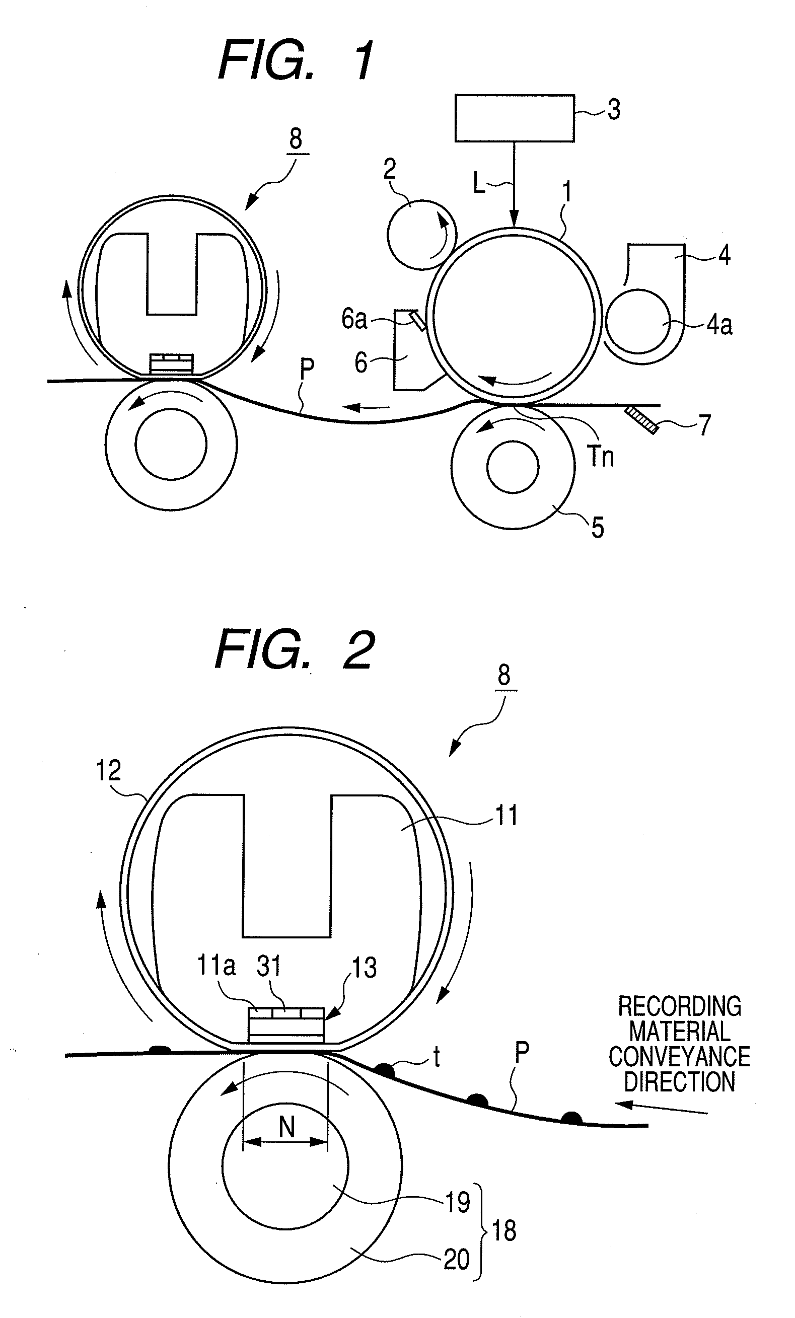
[0031]FIG. 1 is a model diagram illustrating a general structure of an example of an image forming apparatus to which an image heating apparatus according to the present invention can be mounted as an image heat fixing apparatus. The image forming apparatus is a laser beam printer which forms an image on a recording material such as a plain paper, a thick paper, or a resin sheet by using electrophotographic image forming process. A maximum size of the recording material that can be used in this printer is a letter size (216 mm×279 mm). Further, this printer has a structure for conveying the letter size recording material in the state where a long side (279 mm) of the recording material is parallel with a recording material conveyance direction. In addition, a conveying reference of the recording material is a center in a longitudinal direction of a heater of an image heat fixing apparatus that is described later. The printer described in this...
example 1
Heater Example 1
[0069]As the electrode, a silver electrode having A1=2.10E−8 [Ω·m] ((2.1×10⁻⁸) [Ω·m]) was used. As for the heat generation resistive member, ruthenium tetroxide paste having A2=2.60E−2 [Ω·m] and the PTC characteristic of 7 ppm / ° C. was used.
example 2
Heater Example 2
[0070]As the electrode, a silver electrode having A1=3.20E−8 [Ω·m] with silver purity lower than that of Heater example 1 was used. As for the heat generation resistive member, the same material as Heater example 1 was used but only the cross-section was reduced.
PUM
 Abstract
Description
Claims
Application Information