Battery pack

a battery pack and battery technology, applied in secondary cell servicing/maintenance, cell components, vent arrangements, etc., can solve the problems of low electric power density, limited application, risk of inducing smoking and kindling, etc., and achieve the effect of increasing the degree of freedom of mounting position of the battery pack and efficient liquefaction

Inactive Publication Date: 2009-09-03
TDK LAMBDA CORP
View PDF4 Cites 22 Cited by
  • Summary
  • Abstract
  • Description
  • Claims
  • Application Information

AI Technical Summary

Benefits of technology

[0016]According to the battery pack of the present invention, the internal gases generated from the battery cells can be liquefied inside the battery pack. Hence, there is no need to separately take measures for gas processing. Accordingly, the risk-free and easy-to-use battery pack can be realized in which the internal gases evaporated due to an application of overvoltage or the like are processed inside a case of the battery pack to prevent the gases from leaking to the outside of the case and besides the case is free from breaking even if internal pressure of the case has increased due to a thermorunaway of the battery pack.
[0017]Further, according to the battery pack of the present invention, the gas processor is composed of the metallic body having the plurality of the spaces partitioned by the partition walls. Hence, the internal gases can be efficiently liquefied.
[0018]Furthermore, according to the battery pack of the present invention, the internal gases which have inflowed into the gas processor can be sequentially liquefied in the plurality of the spaces partitioned by the partition walls. Hence, the internal gases can be further efficiently liquefied.
[0019]Moreover, according to the battery pack of the present invention, the gas inflow port is located at the position lower than that where the ventilation hole is located. Hence, liquefied gases can be prevented from remaining in the spaces of the metallic body provided with the gas inflow port. Hence, a mounting posture of the battery pack is increased in degree of freedom.
[0020]Further, according to the battery pack of the present invention, a path from a gas discharging portion of the battery cell to the gas exhaust port is elongated. Hence, liquefaction of the gases can be accomplished while the gases are flowing in the path.
[0021]Furthermore, according to the battery pack of the present invention, the gases are allowed to be easy to remain within the spaces sandwiched by the partition walls, so that the gases can be efficiently liquefied and besides the gases liquefied are easy to remain within the spaces.

Problems solved by technology

The lead storage battery, however, uses lead which is a material hazardous to a human body and further has a low electric power density, thus resulting in a limitation in application.
Despite high electric power density as an electricity storage medium, the lithium-cell 1 with the structure like this uses a material which generates a flammable gas at high temperature and hence involves the risk of inducing smoking and kindling if abnormal state such as overcharge or the like occurs in the battery.
If such condition persists, the aluminum laminates 6 are likely to explode, posing a risk.
Further, if the abnormal state such as overcharging or the like continues, the separator 4 inside the lithium cells 1 melts to cause internal short-circuiting between the positive and negative electrodes 2a, 3a, thus posing risk of giving rise to kindling at once.
Then, a pressure rise inside the case causes outward leakage of the internal gases.
At the same time, if the case is formed with an air-tight structure to prevent the gas leakage, internal pressure of the case rises, resulting in a risk for the case to be broken in the worst-case scenario.

Method used


Image

  • Battery pack
  • Battery pack
  • Battery pack

Examples


embodiment 1

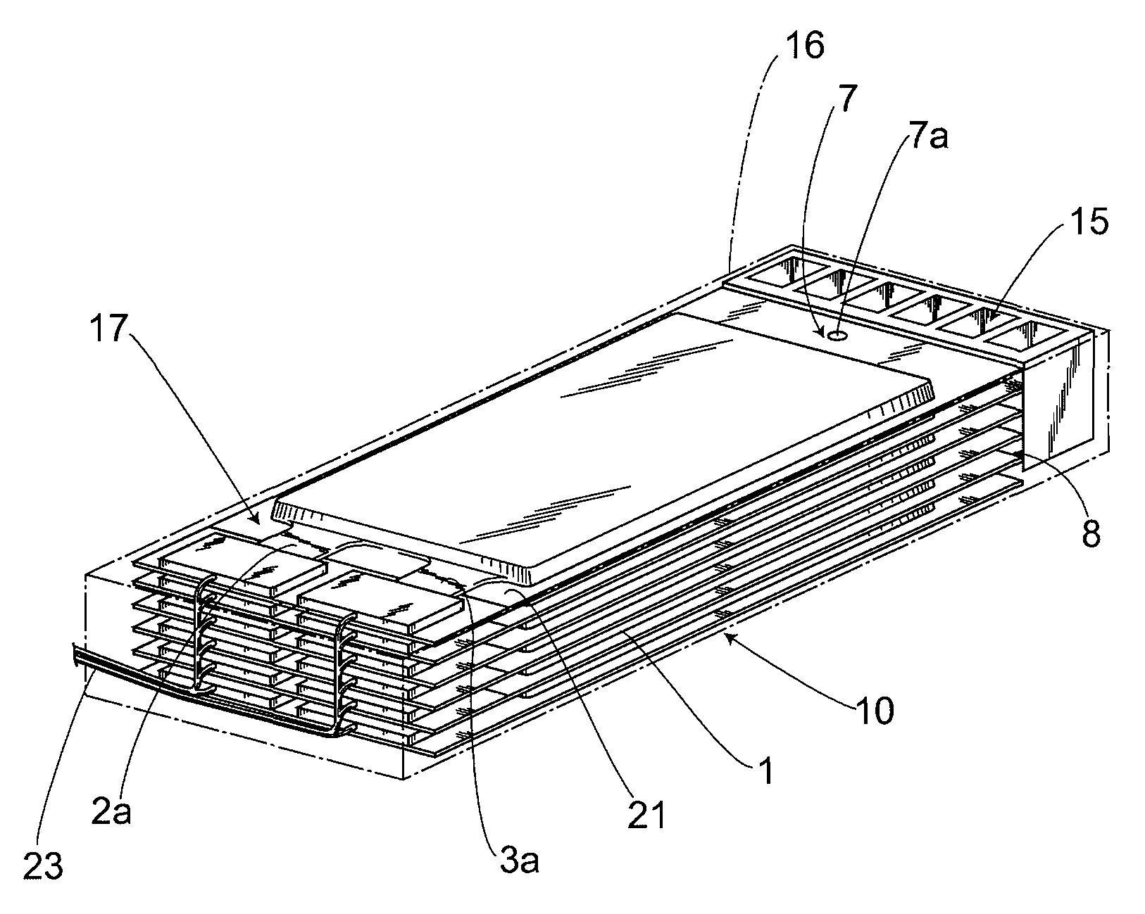
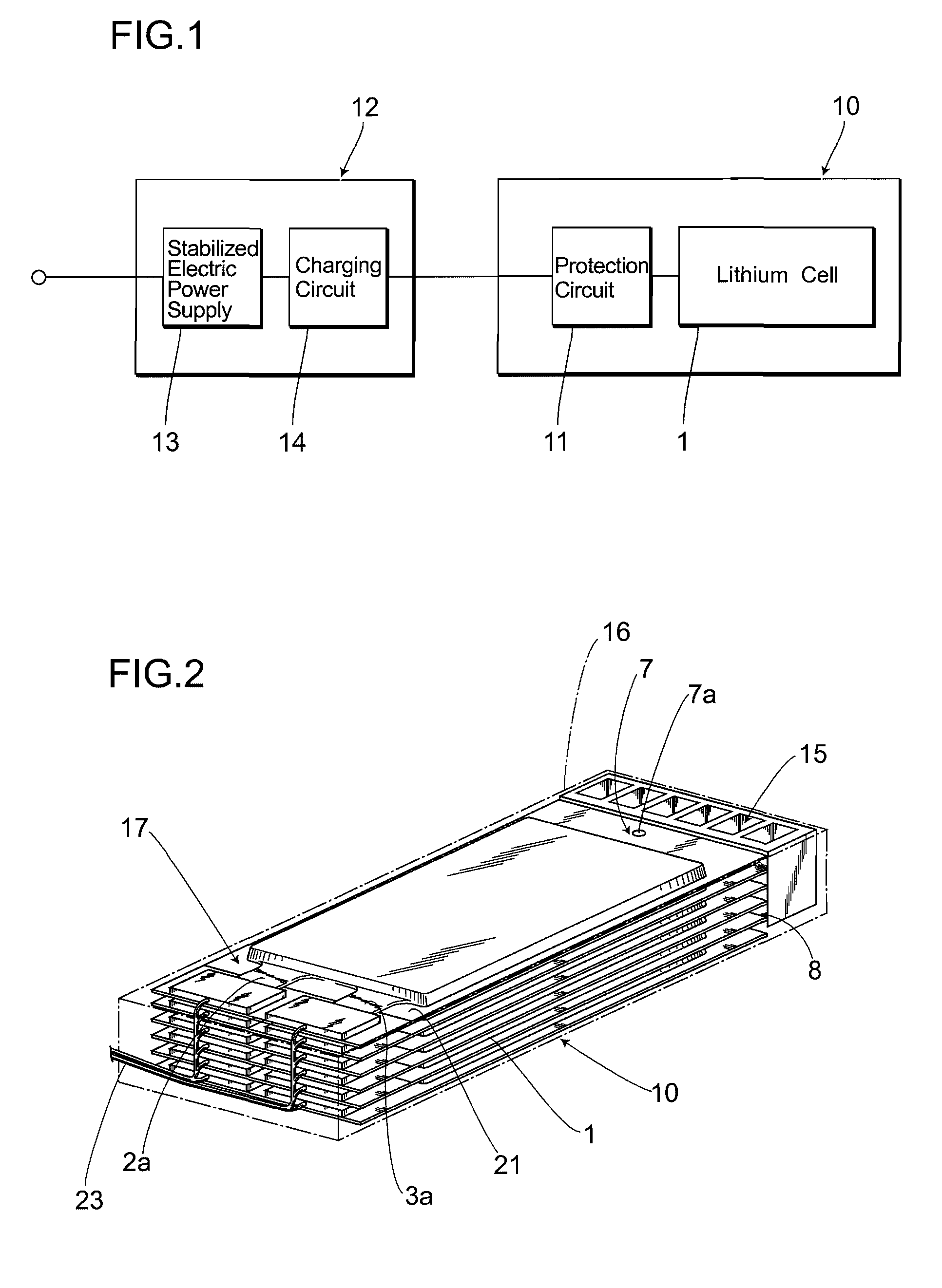
[0025]FIG. 1 is a block diagram representing a battery pack 10 using a lithium cell 1 acting as a battery cell of a chargeable and dischargeable secondary battery and an outline configuration in using the battery pack 10. In the figure, a battery pack 10 is incorporated with lithium cells 1 together with a protection circuit 11. The protection circuit 11 is equipped with, e.g., a current fuse, a temperature fuse, an overvoltage protector or the like to cut off charging electric power fed to the lithium cells 1 in occurrences of overcurrent, overvoltage and abnormal temperature. Obviously, differing from the figure, it is possible to provide the protection circuit 11 and the battery pack 10 separately from each other.

[0026]A battery charger 12 that feeds charging electric power to the lithium cells 1 is connected with a previous stage of the battery pack 10. The battery charger 12 comprises a stabilized power supply 13 that produces stabilized charging electric power and a charging c...

embodiment 2

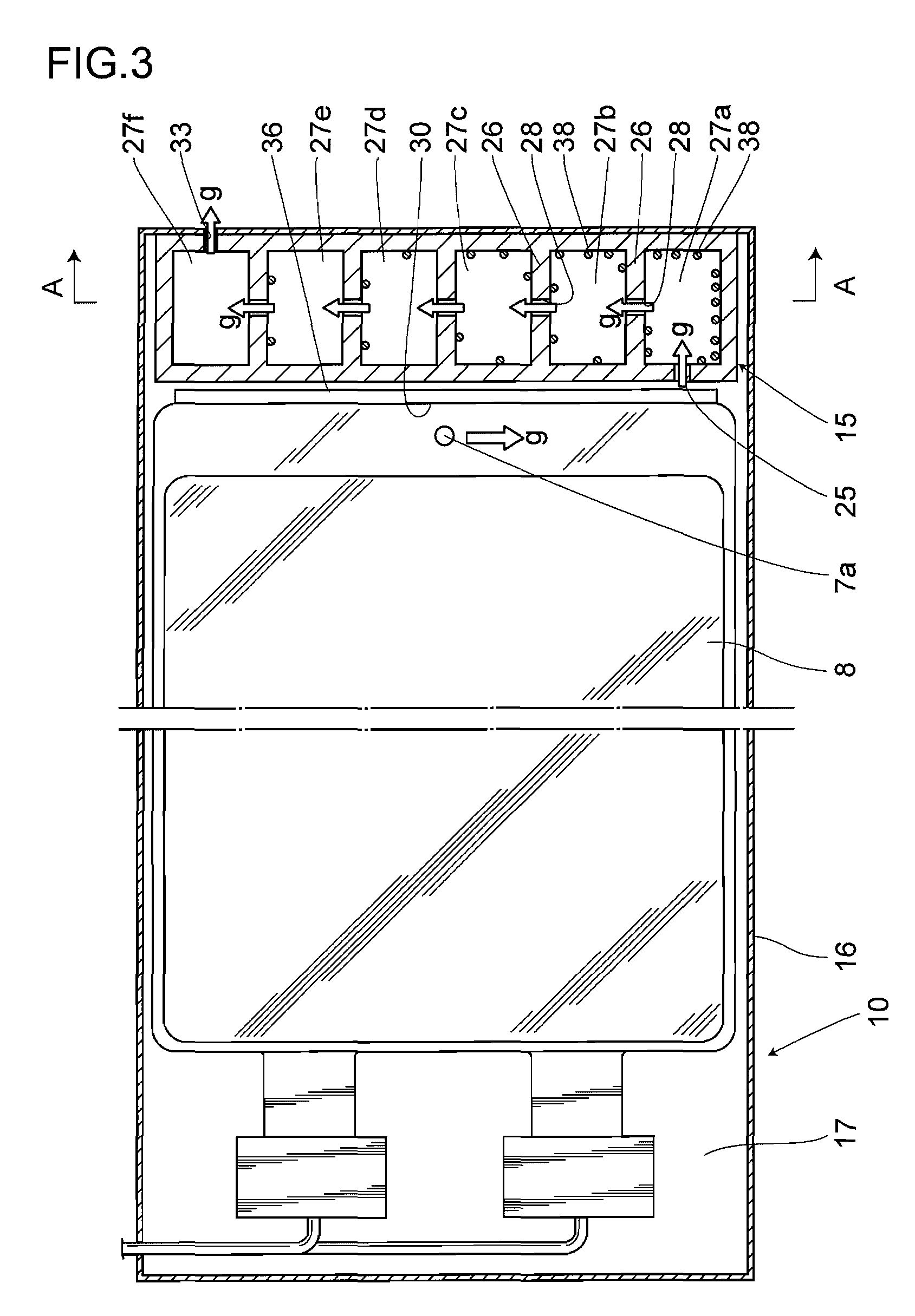
[0041]FIG. 6 represents a plain cross-sectional view of a battery pack 10 in a present second embodiment. The battery pack 10 is the same as that in the first embodiment except a structure of a gas processor 15. The battery pack 10, i.e., includes a battery cell housing 17 that houses a battery stack 8 built up by stacking lithium cells 1 one above the other inside a case 16 of the battery pack, that forms an enclosure of the battery pack, and a gas processor 15 that liquefies gases generated from the lithium cells 1. The gas processor 15 in the present second embodiment is one where a path from a safety valve acting as a discharging portion of the lithium cells 1 to an exhaust port is elongated, so that the gases are liquefied by cooling walls while flowing through the path.

[0042]The gas processor 15 is formed by making a metallic material such as aluminum or the like, that is excellent in thermal conductivity and in exoergic property, into a boxy shape. The battery cell housing 17...

embodiment 3

[0052]FIG. 7 represents a plain cross-sectional view of the battery pack 10 in a present third embodiment. The battery pack 10 is the same as that in the first and second embodiments except a structure of the gas processor 15. The battery pack 10, i.e., includes a battery cell housing 17 that houses a battery stack 8 built up by stacking lithium cells 1 one above the other inside a case 16 of the battery pack, that forms an enclosure of the battery pack, and a gas processor 15 that liquefies gases generated from the lithium cells 1. As in the second embodiment, the gas processor 15 in the present third embodiment is one where a path from a safety valve 7 acting as a discharging portion of the lithium cells 1 to a gas exhaust port of the battery pack is elongated, so that the gases are liquefied by cooling walls while flowing through the path.

[0053]The gas processor 15 is formed by making a metallic material such as aluminum or the like, that is excellent in thermal conductivity and ...


PUM

PropertyMeasurementUnit
rating voltageaaaaaaaaaa
degree of freedomaaaaaaaaaa
thermal resistanceaaaaaaaaaa

Abstract

There is provided a risk-free and easy-to-use battery pack using battery cells 1 as a secondary battery, in which internal gases evaporated by applying overvoltage or the like thereto are processed inside a case to be prevented from leaking to the outside of the case and thereby even if the case has been led to rise in pressure due to a thermorunaway of the battery, the case is free from breaking. To realize this performance, the battery pack 10 is provided with a battery cell housing 17 for housing lithium cells 1 and a gas processor 15 for liquefying the internal gases g generated from the lithium cells 1.

Description

TECHNICAL FIELD[0001]The present invention relates to a battery pack of a chargeable and dischargeable secondary battery such as a lithium-ion battery or the like, which is employed as an electric power supply for various types of electronic devices.BACKGROUND ART[0002]Heretofore, a lead storage battery has been extensively used as a secondary battery. This is due for example to the fact that a lead storage battery can be manufactured at low cost and is comparatively easy-to-use and so on. The lead storage battery, however, uses lead which is a material hazardous to a human body and further has a low electric power density, thus resulting in a limitation in application. Under the situation like this, recently, a lithium-ion battery which has high electric power density as an electricity storage medium and can be reduced in size is coming into wide use. FIG. 8 represents a structure of a laminate-type lithium-ion battery, as a one exemplary configuration of the lithium-ion battery. A...

Claims


Application Information

Patent Timeline
Patent Type & Authority Applications(United States)
IPC IPC(8): H01M10/34H01M50/211
CPCH01M2/1016H01M10/052H01M2/12H01M2/1094Y02E60/10H01M50/30H01M50/24H01M10/658H01M50/211
Inventor NAKAZAWA, HIROSHINAKANE, KATSUHIKO
Owner TDK LAMBDA CORP
Why Eureka
Try Eureka