Eureka AIR delivers breakthrough ideas for toughest innovation challenges, trusted by R&D personnel around the world.

Switching Between the Wireless Communication System Mode and the Satellite Positioning System Mode, Based on the Detected Voice Activity of the Transmitter

Inactive Publication Date: 2009-09-03
NOKIA TECHNOLOGLES OY
View PDF15 Cites 4 Cited by
  • Summary
  • Abstract
  • Description
  • Claims
  • Application Information

AI Technical Summary

Benefits of technology

[0009]The invention has in accordance with one embodiment the advantage that it provides a way to optimise the performance of the communication device with minimal speech quality degradation. The invention makes it possible to switch between satellite system signal reception and communication system signal reception.

Problems solved by technology

Therefore, the receiving end can generate comfort noise based on the received SID frame.
This degrades the performance of both receivers.

Method used


Image

  • Switching Between the Wireless Communication System Mode and the Satellite Positioning System Mode, Based on the Detected Voice Activity of the Transmitter
  • Switching Between the Wireless Communication System Mode and the Satellite Positioning System Mode, Based on the Detected Voice Activity of the Transmitter
  • Switching Between the Wireless Communication System Mode and the Satellite Positioning System Mode, Based on the Detected Voice Activity of the Transmitter

Examples


example 1

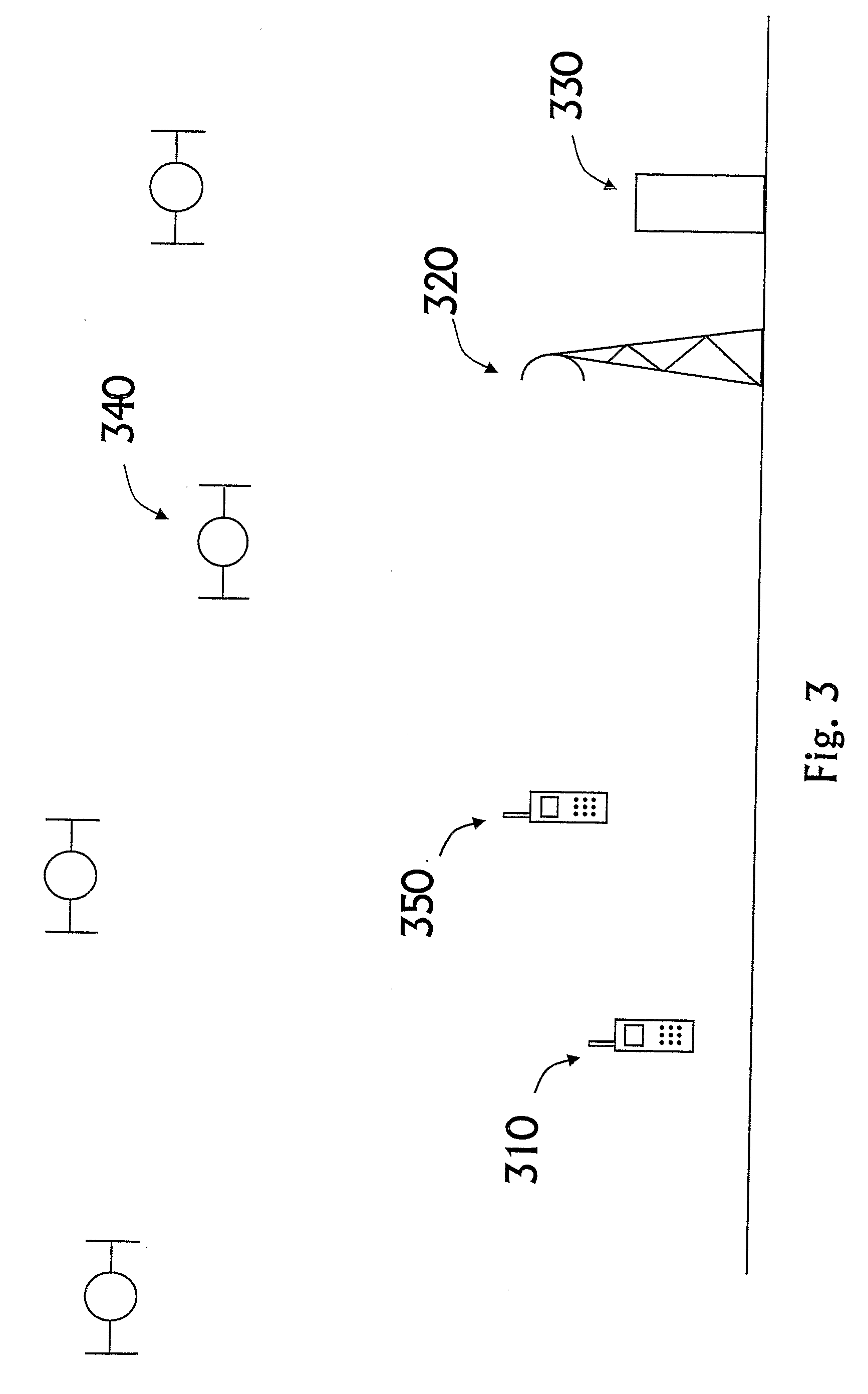
[0038]FIG. 7 shows a more detailed flowchart of the method in accordance with an embodiment of the invention. In this embodiment the VAD 404 is only needed in the transmitting handset 350. At step 701 it is determined that dual mode reception is needed from the satellites 340 and from the transmitting handset 350. At step 702 dual mode reception is started.

[0039]At step 703 the receiving handset 310 functions in transmitting handset active mode. In transmitting handset active mode the GNSS reception part is active, for instance, 100 ms in a second. In this case cellular system signal reception would be active a majority of the time, for instance 900 ms in a second. This is illustrated in FIG. 8. When the receiving handset 310 determines that the transmitting end 350 is active the handset can operate in cellular system mode. The handset can remain in this mode 900 ms at a time according to this exemplary embodiment. During this period, no signals from the satellite system are receive...

example 2

[0043]FIG. 10 presents another embodiment to implement the invention. In this embodiment VAD 404 is needed in both handsets 310 and 350. At step 1001 it is determined that dual mode reception is needed from the satellites 340 and from the transmitting handset 350. At step 1002 dual mode reception is started.

[0044]At step 1003 the receiving handset 310 functions in transmitting handset active mode. In transmitting handset active mode the GNSS reception part is active for instance 100 ms in a second. In this case cellular reception would be active majority of the time, for instance 900 ms in every second. Also other suitable active periods for the different reception parts can be used.

[0045]Then at step 1004 it is determined whether dual mode reception is needed. If there is no need for dual mode reception, then at step 1012 the dual mode reception can be terminated. If however the dual mode reception is needed, then at step 1005 the receiving handset 310 determines whether the transm...


PUM


Abstract

A method for a first wireless communication device to operate in wireless communication system mode and satellite positioning system mode. The first wireless communication device communicates with a second communication device. Voice activity of at least one of the communication devices is determined and based on the determined voice activity, the first wireless communication device switches between wireless communication system mode and satellite positioning system mode. The voice activity can be determined by using voice activity detector in at least one of the communication devices.

Description

FIELD OF THE INVENTION[0001]Embodiments of the invention relate to a combined global navigation satellite system (GNSS) receiver and cellular system receiver. More specifically embodiments of the invention relate to a receiver in which the radio path between GNSS and cellular system signals can be shared. Embodiments of the invention also relate to a corresponding method, system, module and computer program product.BACKGROUND OF THE INVENTION[0002]In cellular systems, different multiple access techniques can be applied depending on the cellular system standard. In the global system for mobile communications (GSM), combined time and frequency division multiple access techniques are applied (TDMA / FDMA). The FDMA technique involves the division of the 25 MHz bandwidth into 124 carrier frequencies spaced 200 kHz apart. Several carrier frequencies can be assigned to each base station (BS). According to the TDMA technique, these carrier frequencies are then divided in the time domain. The...

Claims


Application Information

Patent Timeline
IPC IPC(8): H04M1/00H04B1/69G01S19/36H04W88/06
CPCG01S19/36H04B1/3805H04W88/06H04M2250/10H04M1/72519H04M1/724
Inventor PIETILA, SAMULIEEROLA, VILLE A.VALIO, HARRI MATTI JOHANNES
Owner NOKIA TECHNOLOGLES OY
Why Eureka
Eureka Blog
Learn More