Transfemoral prosthetic systems and methods for operating the same

a transfemoral and prosthetic technology, applied in the field of prosthetic and orthotic limbs, can solve the problems of high energy expenditure on the part of the disabled person or amputee, inability to take into account the dynamic conditions of the working environment, and inability to adjust the gait, etc., to achieve more natural and comfortable movement, convenient and intuitive configuration, and the effect of adding

Active Publication Date: 2009-09-03
OSSUR HF
View PDF96 Cites 143 Cited by
  • Summary
  • Abstract
  • Description
  • Claims
  • Application Information

AI Technical Summary

Benefits of technology

[0014]In one embodiment, a prosthetic or orthotic system is provided having an ankle-motion-controlled foot. The prosthetic or orthotic system comprises, among other things, a lower limb member, an actuator, and a foot unit. The actuator is configured to mimic the motion of an ankle by adjusting the angle between the lower limb member and the foot unit. The prosthetic or orthotic system also comprises an attachment portion that facilitates coupling of the lower limb member to another prosthetic or orthotic member, to the stump of an amputee, or to another component. The prosthetic or orthotic system may also comprise a rechargeable battery to provide power to the actuator or other components of the system. Embodiments of the invention include systems for both transtibial and transfemoral amputees.
[0060]After considering this discussion, and particularly after reading the section entitled “Detailed Description of Certain Embodiments” one will understand how the features of this invention provide advantages that include providing a prosthetic or orthotic control system that provides more natural and comfortable movement to its users and enabling a more convenient and intuitive configuration, addition, replacement, or augmentation of control system software.

Problems solved by technology

Such basic controllers do not take into consideration the dynamic conditions of the working environment.
The passive nature of these conventional prosthetic and orthotic devices typically leads to movement instability, high energy expenditure on the part of the disabled person or amputee, gait deviations and other short- and long-term negative effects.
However, advances in electronics appear to have outpaced the advances in control systems.
Operating in isolation from each other, multiple control systems may fail to provide the patient with stable, coordinated movement.
In addition, independent configuration of multiple prosthetic devices can be inconvenient.

Method used


Image

  • Transfemoral prosthetic systems and methods for operating the same
  • Transfemoral prosthetic systems and methods for operating the same
  • Transfemoral prosthetic systems and methods for operating the same

Examples


Embodiment Construction

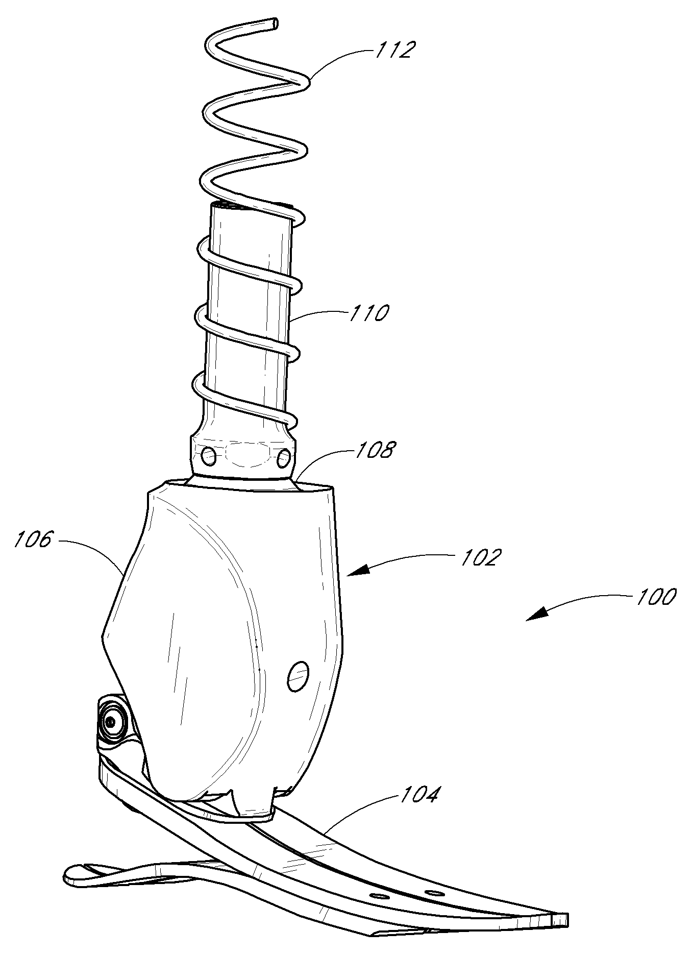
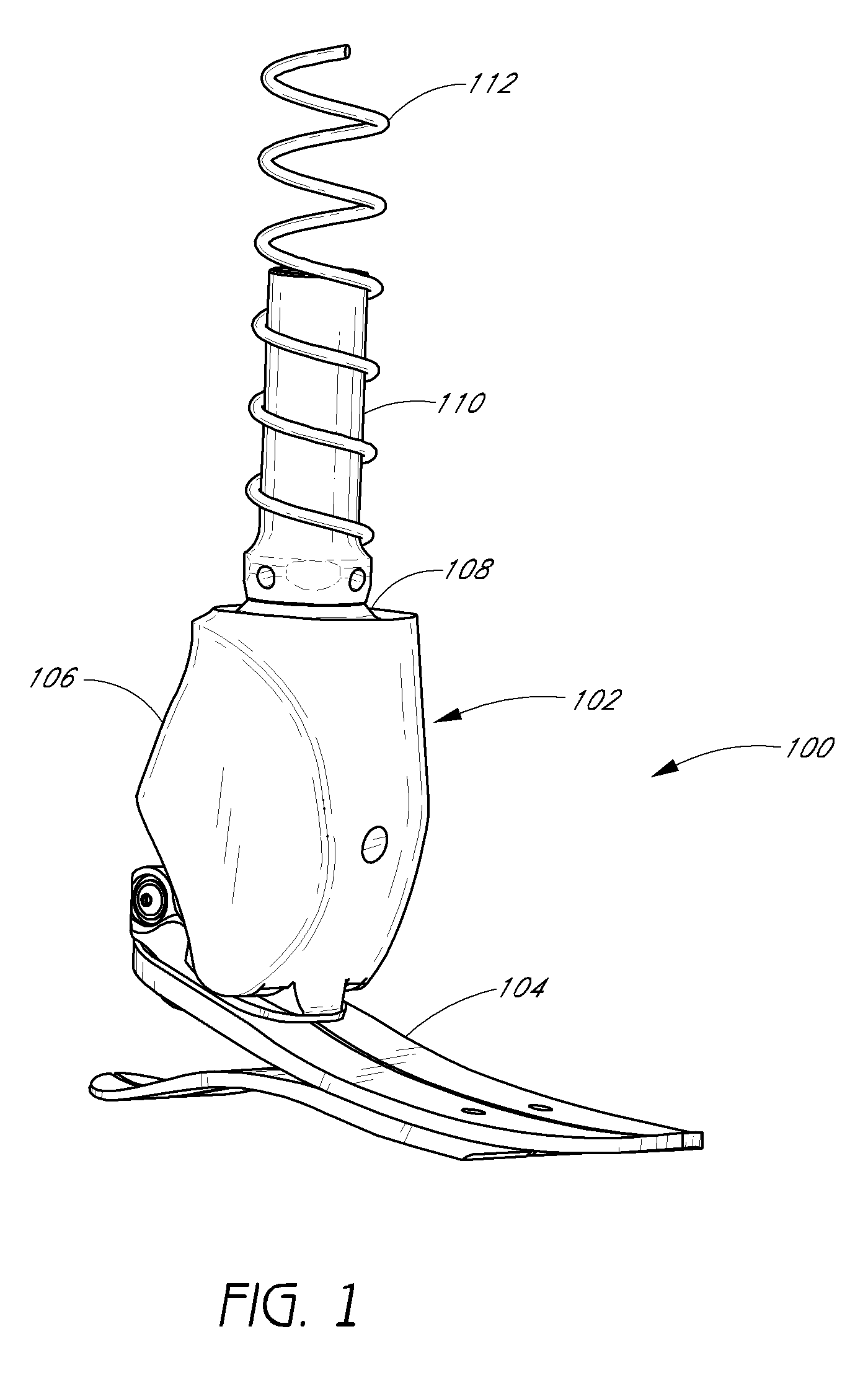
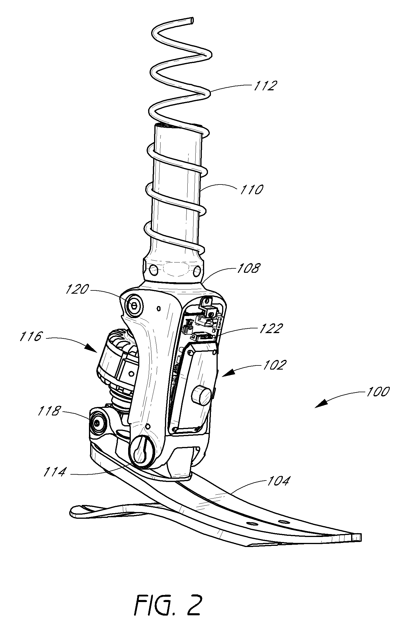
[0009]Accordingly, one embodiment of the invention includes a prosthetic or orthotic system that is self-powered and that mimics the natural movement of a healthy limb, and in particular, the movement of a healthy ankle. Another embodiment of the invention includes a sensor system and a control system that manage the motion of the prosthetic or orthotic system so as to facilitate movement by the disabled person or amputee.

[0010]One embodiment of the invention includes a system associated with the movement of a limb. In one embodiment, the system comprises a foot unit; an attachment member having an upper end and a lower end, wherein the lower end is pivotably attached to a first location on the foot unit; and an actuator operatively coupled to the foot unit and to the attachment member, wherein the actuator is configured to actively adjust an angle between the attachment member and the foot unit. For example, the foot unit may be a prosthetic or orthotic device.

[0011]Another embodim...


PUM


Abstract

Certain embodiments of the invention relate to increasing the functionality of a transfemoral prosthetic device. In one embodiment, the transfemoral prosthetic device is configured such that the prosthetic knee maintains a load consistent with a healthy knee walking on level ground, while the prosthetic ankle adjusts for the incline or decline. In certain embodiments, adjustments, such as a toe lift function, are automatically performed after about three strides of the transfemoral prosthetic device user and / or when each of the strides has a stride speed of at least about 0.55 meters / second.

Description

RELATED APPLICATIONS[0001]This application claims the benefit of U.S. Provisional Application No. 61 / 039,055, filed Mar. 24, 2008; is a continuation-in-part of U.S. patent application Ser. No. 11 / 355,047 (Attorney Docket No. OSSUR.061A), filed Feb. 15, 2006; which claims priority to U.S. Provisional Application Nos. 60 / 653,717 and 60 / 679,953, filed Feb. 16, 2005 and May 10, 2005, respectively; and is a continuation-in-part of U.S. patent application Ser. No. 11 / 056,344 (Attorney Docket No. OSSUR.053A), filed Feb. 11, 2005; which claims priority to U.S. Provisional Application Nos. 60 / 544,259 and 60 / 588,232, filed Feb. 12, 2004 and Jul. 15, 2004, respectively. Each of the above mentioned applications is incorporated herein by reference in its entirety and should be considered part of this specification.BACKGROUND[0002]1. Field of the Invention[0003]The present invention relates to prosthetic and orthotic limbs in general and, in addition, to systems and methods for configuring, synch...

Claims


Application Information

Patent Timeline
Patent Type & Authority Applications(United States)
IPC IPC(8): A61F2/74A61F2/66
CPCA61F2/60A61F2002/769A61F2/6607A61F2/68A61F2/72A61F2002/5004A61F2002/5006A61F2002/5018A61F2002/607A61F2002/701A61F2002/704A61F2002/705A61F2002/7625A61F2002/763A61F2002/7635A61F2002/764A61F2002/768A61F2002/7685A61F2/64A61F2/70
Inventor CLAUSEN, ARINBJORN VIGGO
Owner OSSUR HF
Why Eureka
Try Eureka