Communication system, communication apparatus, communication program, and computer-readable storage medium stored with the communication program

Active Publication Date: 2009-09-03
SONY COMPUTER ENTERTAINMENT INC
View PDF19 Cites 74 Cited by
  • Summary
  • Abstract
  • Description
  • Claims
  • Application Information

AI Technical Summary

Benefits of technology

[0006]According to the present invention, reduction in transmission efficiency may be prevented even if the number of communicat

Problems solved by technology

However, with such a system, there is a possibility that transmission quantity of data to be transmitted or received increases each time the number of people participating in the co

Method used


Image

  • Communication system, communication apparatus, communication program, and computer-readable storage medium stored with the communication program
  • Communication system, communication apparatus, communication program, and computer-readable storage medium stored with the communication program
  • Communication system, communication apparatus, communication program, and computer-readable storage medium stored with the communication program

Examples


embodiments

(1) Structure

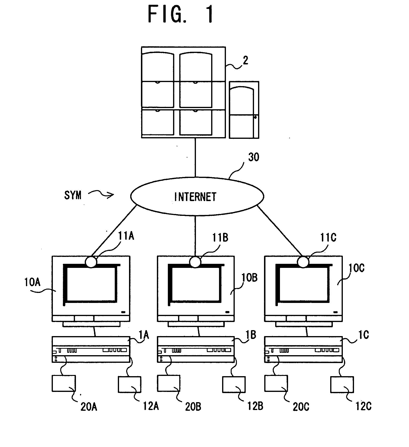
[0048]FIG. 1 is a diagram showing an outline of an AV chat system SYM according to this embodiment. The AV chat system SYM includes multiple client apparatus 1A, 1B, and 1C and a server apparatus 2. The server apparatus 2 conducts data communication with each of the client apparatus 1 via the Internet 30. The multiple client apparatus 1A, 1B, and 1C communicate with each other using a peer-to-peer (P2P) protocol. Note that users of these client apparatus 1A, 1B, and 1C are referred to as users A, B, and C here. Hereafter, the client apparatus 1A, 1B, and 1C are simply referred to as client apparatus 1 when it is unnecessary to distinguish them. In contrast, when the respective client apparatus need to be distinguished from each other and further when components comprising each client apparatus need to be distinguished from each other, A, B, and C are appended at the end of the respective reference numerals.

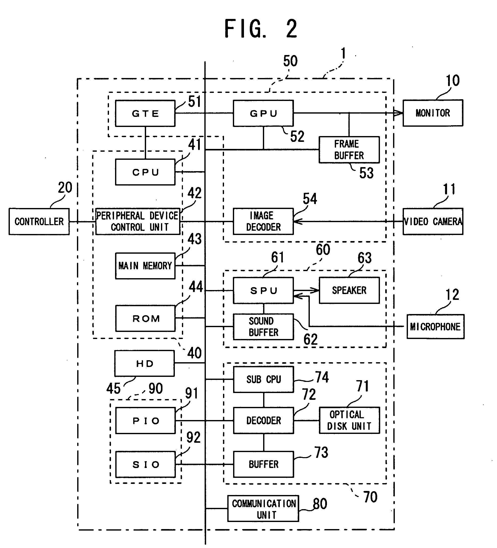
[0049]A controller 20, a monitor 10, a video camera 11, and a mi...

modified examples

Modified Example 1

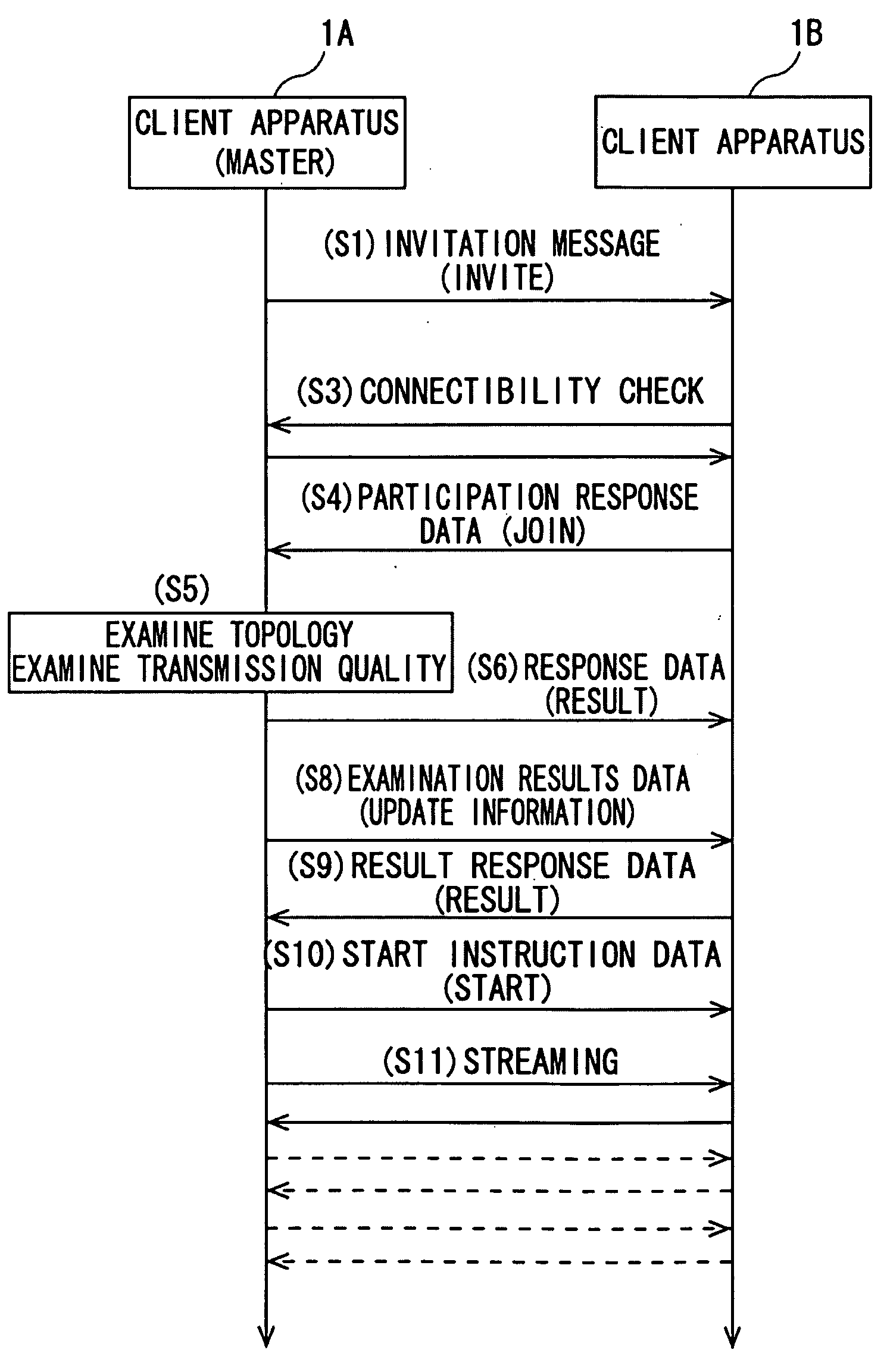
[0097]When deciding the aforementioned transmission quality, the correspondence relationships of number of participating users and transmission quality may be made to differ, for example, according to image quality of the chat screen displayed on the monitor 10. For example, a structure capable of setting image quality of the chat screen displayed on the monitor 10 to either high quality mode or standard quality mode may be provided. In Step S5, S25, or S45, transmission quality is then decided according to the correspondence relationships given in FIG. 8 in the case of high quality mode while it is decided according to the correspondence relationships given in FIG. 17 in the case of standard quality mode.

[0098]Moreover, resolution and transmission frequency are used as the transmission quality of the video data in the above embodiment. However, the present invention is not limited to this, and video (image) compression rate, color variation representing images, a...

modified example 2

[0099]Alternatively, the transmission quality may be decided according to profile information of the respective client apparatus 1 in the aforementioned Steps S5, S25, and S45. The profile information indicates connection environment and processing environment for the client apparatus. More specifically, for example, the connection environment indicates transmission band in which data transmission and reception are carried out. The processing environment indicates CPU availability, and consumable amount of memory such as the main memory 43. For example, when the client apparatus 1 includes a multiprocessor system, CPU availability may indicate available number of sub processors. For example, in FIG. 18, the connection environment is divided into two: case where the transmission band is 500 kbps or greater (broad band) and case where it is less than 500 kbps (narrow band). Moreover, the processing environment is divided into two: high-consumption environment and low-consumption envir...


PUM


Abstract

Multiple client apparatus 1 belonging to a predetermined communication group connected to the Internet 30 transmit and receive with each other video data corresponding to an image videotaped by a video camera 11 and audio data corresponding to voice input from a microphone 12. One of the multiple client apparatus 1 determines the number of client apparatus 1 belonging to the communication group, and decides transmission quality of the video data according to the determined number. The multiple client apparatus 1 belonging to the communication group transmits the video data according to the transmission quality.

Description

TECHNICAL FIELD[0001]The present invention relates to optimum techniques utilized for communication systems of transmitting and receiving video data and audio data among multiple communication apparatus.BACKGROUND ART[0002]Conventionally, there has been a remote conference system of transmitting and receiving audio data and video data in real time among multiple remote conference apparatus connected to a network (e.g., Patent Document 1). With such a system, a user may engage in a conversation in real time while viewing a video image of another user, and may participate in a conference while at a distance.Patent Document 1: Japanese Unexamined Patent Application Publication No. 2001-57672 DISCLOSURE OF THE INVENTIONProblem to be Solved by the Invention[0003]However, with such a system, there is a possibility that transmission quantity of data to be transmitted or received increases each time the number of people participating in the conference increases. Therefore, the data transmis...

Claims


Application Information

Patent Timeline
IPC IPC(8): G06F15/16
CPCH04L12/185H04N7/148H04N7/147H04L12/58H04L51/10H04N7/15H04N7/14H04M3/56H04L51/00
Inventor FUJIHARA, MASAHIRO
Owner SONY COMPUTER ENTERTAINMENT INC
Why Eureka
Try Eureka