[0013]The present invention, in certain aspects, provides an item, apparatus, or tubular, e.g. a piece of
drill pipe, with one or more
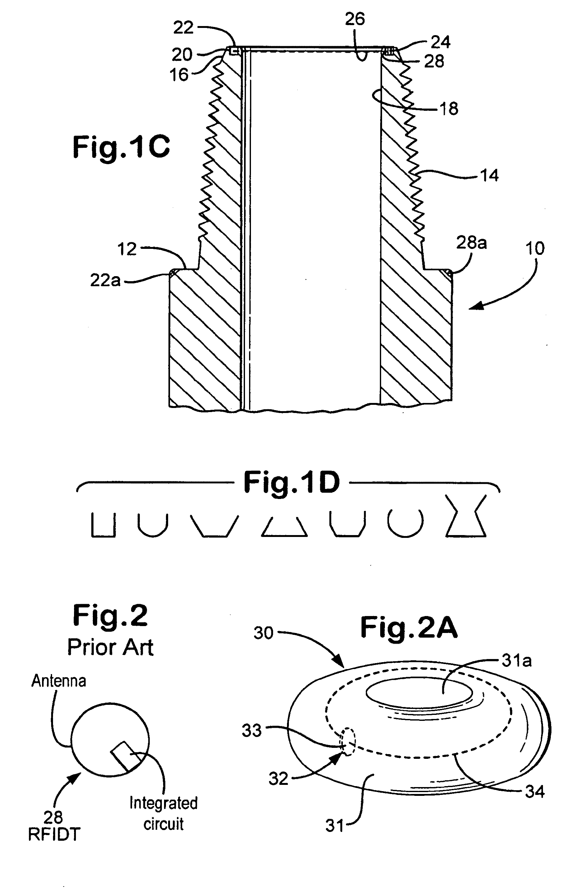
radio frequency identification tags wrapped in heat and
impact resistant materials; in one aspect, located in an area 2-3″ in length beginning ½ from the 18 degree taper of the pin and
drill pipe tool joint so that the RFIDT (or RFIDT's) is protected from shocks (pressure, impacts, thermal) that may be encountered on a rig, in a
wellbore, or during
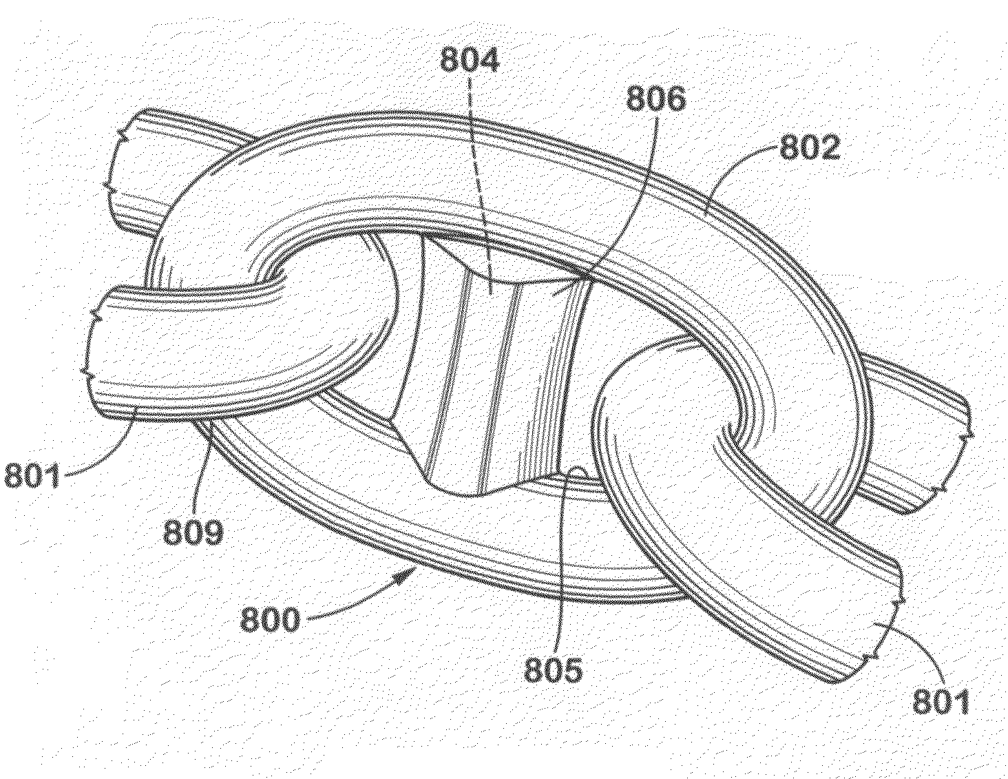
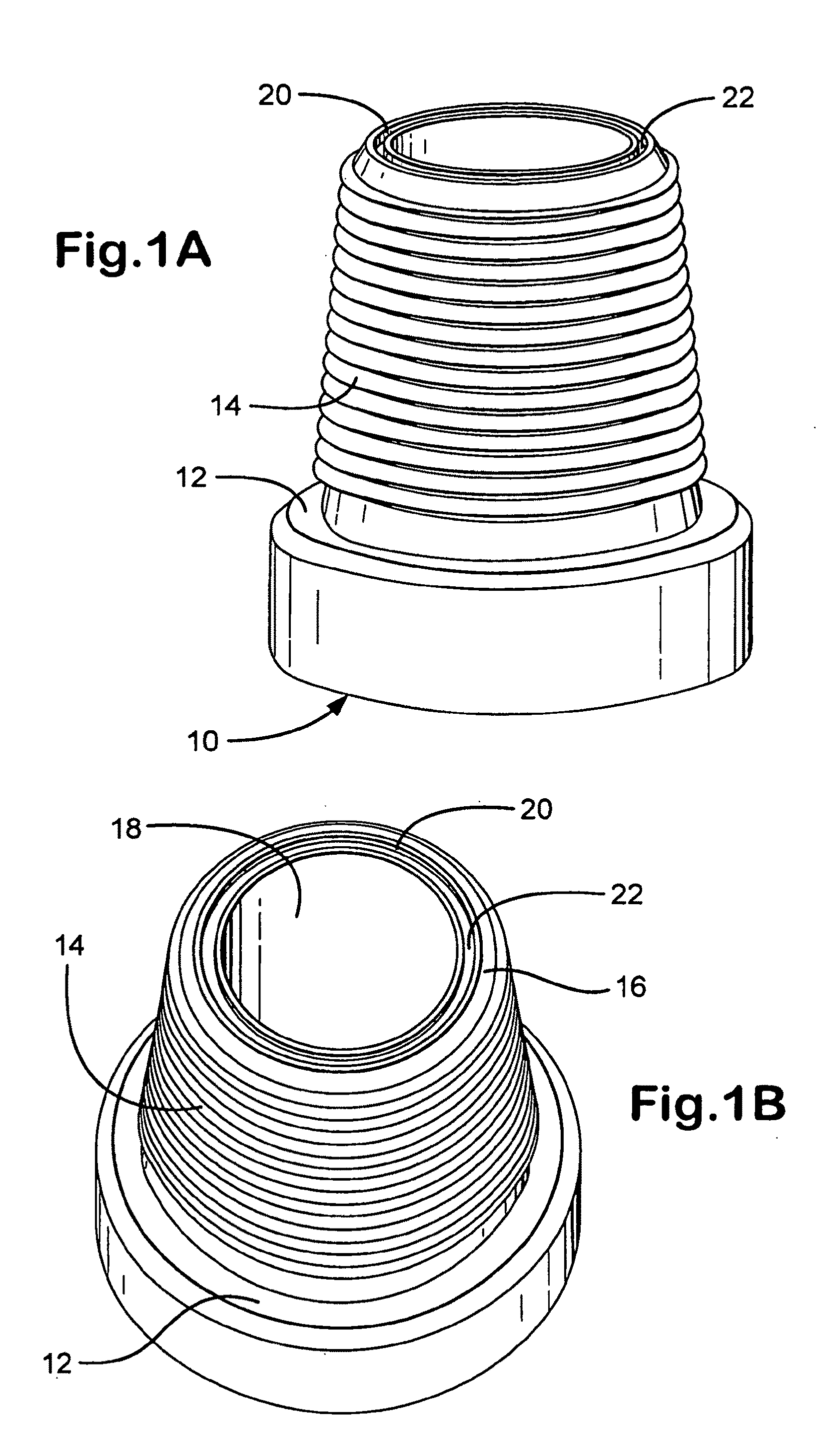
wellbore (e.g. drilling or casing) operations. In one particular aspect, the present invention discloses systems and methods in which a piece of drill pie with threaded pin and box ends has one or more
radio frequency identification tags each with an
integrated circuit and with an antenna encircling the pin end upset area located exteriorly on the pipe, e.g. in an area ½″-2½″ from a pin end 18 degree taper. The RFIDT (or RFIDT's) is protected by wrapping the entire RFIDT and antenna in a
heat resistant material wrapped around the circumference of the tube body and held in place by
heat resistant glue or
adhesive, e.g.
epoxy material which encases the RFIDT. This material is covered with a layer of
impact resistant material and wrapped with multiple
layers of wrapping material such as
epoxy bonded wrap material. Preferably this wrapping does not exceed the tool joint OD. The RFIDT can be (as can be any disclosed herein), in certain aspects, any known commercially-available read-only or read-write
radio frequency identification tag and any suitable know reader
system, manual, fixed, and / or automatic may be used to read the RFIDT. Such installation of RFIDT's can be carried out in the field, in a factory, on a rig, with no
machining necessary. Optionally, a
metal tag designating a unique serial number of each item, apparatus, or length of
drill pipe located under the wrap with the RFIDT(s) insures “
Traceability” is never lost due to failure of the RFIDT(s). Replacement of failed RFIDT's can be carried out without leaving a location, eliminating expensive transportation or trucking costs. Optionally the wrap is applied in a distinctive and / or a bright color for easy identification. Determining whether an item, apparatus, or a tubular or a length of
drill pipe or a
drill pipe string is RFID-tagged or not is visibly noticeable, e.g. from a distance once the RFIDT's are in place.
[0015]With an RFIDT located in a pipe's pin end as described herein, upon makeup of a joint including two such pieces of pipe, an RFIDT in one pipe's pin end is completely surrounded by pipe material—including that of a corresponding pipe'
s box end—and the RFIDT is sealingly protected from access by materials flowing through the pipe and from materials exterior to the pipe. The
mass of pipe material surrounding the enclosed RFIDT also protects it from the temperature extremes of materials within and outside of the pipe.

