
Device and method for quantifying a surface's cleanliness

Active Publication Date: 2009-09-10
LAWLESS JOHN L
View PDF5 Cites 52 Cited by
  • Summary
  • Abstract
  • Description
  • Claims
  • Application Information

AI Technical Summary

Problems solved by technology

In numerous industries, surface contamination and measurement thereof are issues of utmost importance.
Often, cutting processes leave oil residues on the metal parts.
Oil residues may interfere with the adhesion of paint to the metal parts.
Surface purity is also an important issue in facilities that handle reactive chemicals.
Similarly, in environments that are repeatedly exposed to large quantities of fluorine, e.g., reaction chambers of chemical lasers that use hydrogen fluoride and / or deuterium fluoride, cleanliness is a critical issue since the fluorine compounds may be highly reactive in nature and may explode upon contact with contaminants.
Otherwise, catastrophic results may occur due to adhesion failure.
In general, NVR testing is procedurally difficult.
Such testing may also be time consuming.
When the NVR testing facility is remotely located relative to the location of the surface to be tested, it may take days to receive results of such testing.
To ensure that the surface does not become contaminated by the time NVR test results arrive, the surface may have to be isolated and stored in controlled environments such as clean rooms, thereby increasing the costs associated with cleanliness validation.
Furthermore, such testing results occasionally in gross errors.
However, such techniques are accompanies with numerous limitations.
In general, black light has not been known to be useful for detecting contaminants such as light machine and tapping oils, hydraulic oil and silicone room-temperature vulcanizer (RTV) compounds that do not fluoresce strongly at low levels of contamination.
In addition, black-light inspection is subjective, not quantitative and creates no record that is analyzable relative to accepted electronic standards.
The few quantitative technologies that have been used to determine the cleanliness of a surface are generally limited in nature.

Method used


Image

  • Device and method for quantifying a surface's cleanliness
  • Device and method for quantifying a surface's cleanliness
  • Device and method for quantifying a surface's cleanliness

Examples


Embodiment Construction

[0030]Definitions and Overview

[0031]Before describing the invention in detail, it must be noted that, as used in this specification and the appended claims, the singular forms “a,”“an,” and “the” include plural referents unless the context clearly dictates otherwise. Thus, for example, reference to “a contaminant” includes one or more contaminants, reference to “a parameter relevant to bondability” includes a single parameter relevant to bondability as well as a collection of parameters relevant to bondability, reference to “a wavelength” includes a single wavelength as well as a range of wavelengths, and the like.

[0032]In describing and claiming the present invention, the following terminology will be used in accordance with the definitions set out below.

[0033]The term “black light” as used herein refers to radiation invisible to the naked human eye, typically of ultraviolet (UV) or infrared (IR) wavelengths, that causes fluorescent materials to emit radiation of a different wavele...


PUM

PropertyMeasurementUnit
Wavelengthaaaaaaaaaa
Concentrationaaaaaaaaaa
Surface areaaaaaaaaaaa

Abstract

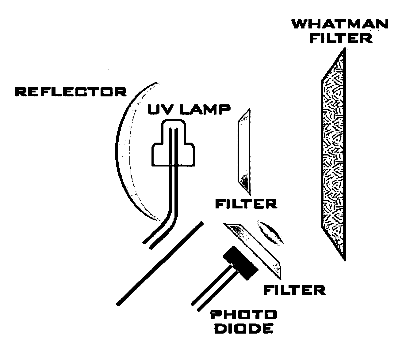
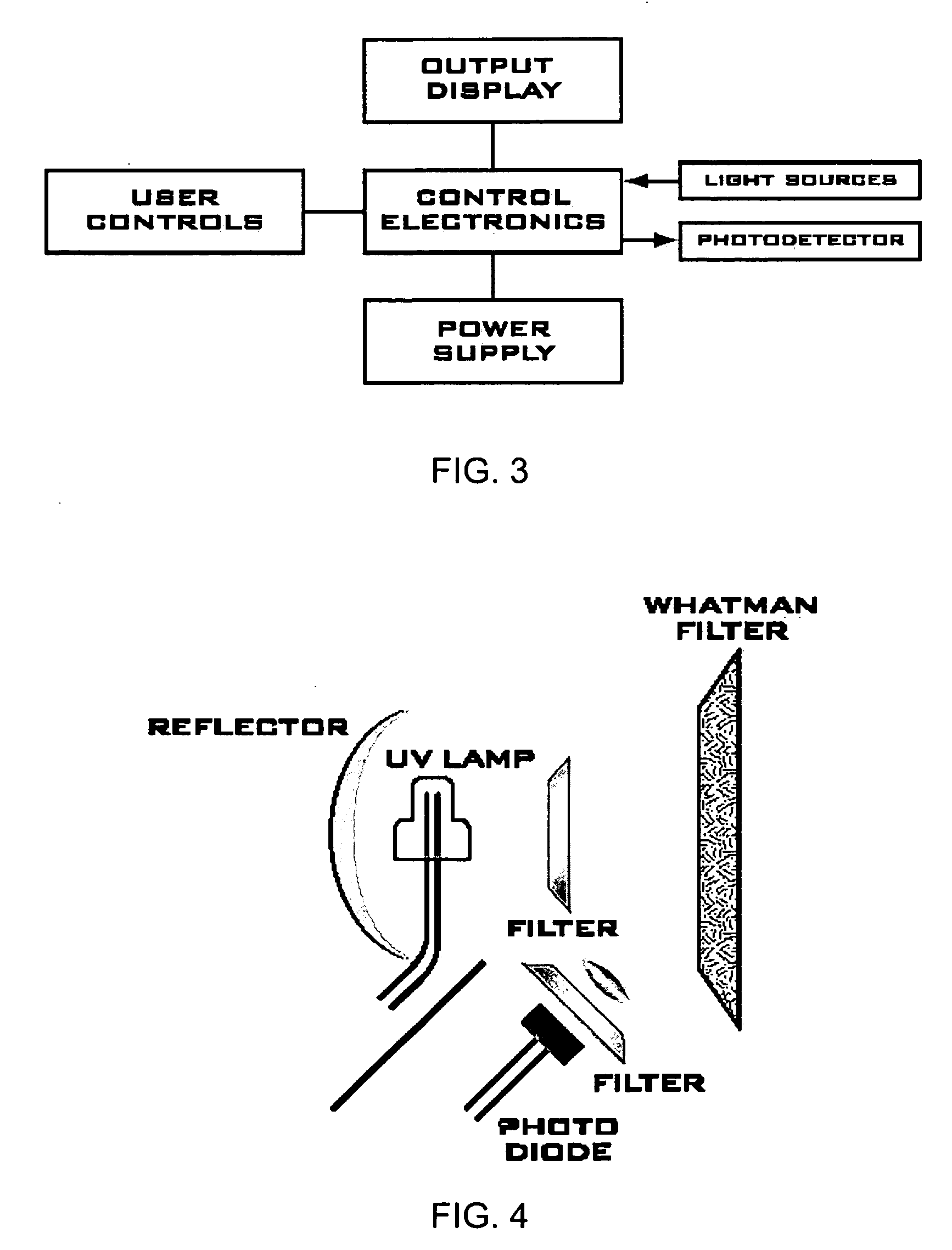
Provided are devices and methods for quantifying a surface's cleanliness relative to a contaminant. Such devices and methods may comprising and use a source of interrogating radiation to which the contaminant is responsive, a means for directing the interrogating radiation, a detector, and an analyzer. Radiation emitted from the source is directed by the radiation means toward the surface or a surface cleaner that may hold the contaminant. The detector detects radiation from the surface or the surface cleaner produced in response to the interrogating radiation by the contaminant, e.g., fluorescent or phosphorescent radiation, and generate a corresponding signal that is compared by the analyzer relative to an electronic standard that corresponds to the surface in an acceptably clean state so as to quantify the surface's cleanliness.

Description

CROSS REFERENCE TO RELATED APPLICATIONS[0001]This application claims priority to U.S. Provisional Application Ser. No. 61 / 034,977, entitled “Device and Method for Quantifying a Surface's Cleanliness,” filed on Mar. 8, 2008, by inventor John L. Lawless, the disclosure of which is hereby incorporated by reference in its entirety.BACKGROUND[0002]1. Technical Field[0003]The present invention generally relates to devices and methods for quantifying a surface's cleanliness. In particular, the invention relates to such and methods that direct interrogating radiation toward a surface or a surface cleaner detecting radiation from the surface or the surface cleaner produced in response to the interrogating radiation.[0004]2. Related Art[0005]In numerous industries, surface contamination and measurement thereof are issues of utmost importance. For example, the manufacturing of painted metal articles may require metal parts to be cut before they are painted. Often, cutting processes leave oil r...

Claims


Application Information

Patent Timeline
IPC IPC(8): B32B37/00G01J5/02G01J1/44G01T1/16G01J1/42
CPCG01N21/05G01N21/47G01N21/55G01N2021/6417G01N21/94G01N2021/0346G01N21/64
Inventor LAWLESS, JOHN L.
Owner LAWLESS JOHN L
Learn More