Brushless motor

a brushless motor and motor body technology, applied in the direction of dynamo-electric machines, magnetic circuit rotating parts, magnetic circuit shapes/forms/construction, etc., can solve the problems of inability to skew magnetization of segment magnets (right-angled magnetic field type magnets), and inability to reduce cogging torque so much, so as to suppress cogging torque and torque ripples, and prevent short-cut magnetic fluxes

Active Publication Date: 2009-09-10
MITSUBA CORP
View PDF8 Cites 31 Cited by
  • Summary
  • Abstract
  • Description
  • Claims
  • Application Information

AI Technical Summary

Benefits of technology

[0012]A motor of the 2P3S−n structure, according to this invention, may have a three-stage skew structure and a skew angle of 60° to 75° in terms of electrical angle. The few poles and few slots brushless motor can then generate a larger output than any rotor-skew motor, while suppressing cogging torque and torque ripples.
[0013]In the brushless motor, each of the segment magnets has each a center angle θm expressed as (140×n−1)°≦θm≦(159×n−1)°. The magnets of each column are thereby arranged, not overlapping the magnets of any adjacent column in the circumferential direction, preventing magnetic fluxes from being short cut. This prevents the motor output from decreasing caused by the decrease of magnetic fluxes. Since the brushless motor achieves low cogging torque, low torque ripple and a large output in good balance, it is fit for use as a drive source in electric power steering apparatuses. If used in an electric power steering apparatus, the brushless motor can serve to make the electric power steering apparatus small and light without degrading steering feeling.

Problems solved by technology

However, the segment magnets (right-angled magnetic field type magnets) cannot be skew-magnetized due to the restriction imposed on its manufacture.
Inevitably, the cogging torque cannot be reduced so much in the two-staged, step-skew structure.
The cogging torque can hardly be reduced, particularly in any motor that has a few poles and a few slots because the least common multiple of the number of poles and the number of slots is small, inevitably increasing the influence of the variation.
In view of this, accuracy of the magnets and parts assembling are very strict, the motor cannot be as robust as desired.
In case the magnets having different polarity overlap each other, the magnetic fluxes will be cut short, as a result, effective fluxes required for driving the motor will not be provided.
Consequently, the skew angle will not be increased, as a result, the cogging torque and the like cannot be reduced enough, and the effective fluxes decrease to result in a small motor output.

Method used


Image

  • Brushless motor
  • Brushless motor
  • Brushless motor

Examples


Embodiment Construction

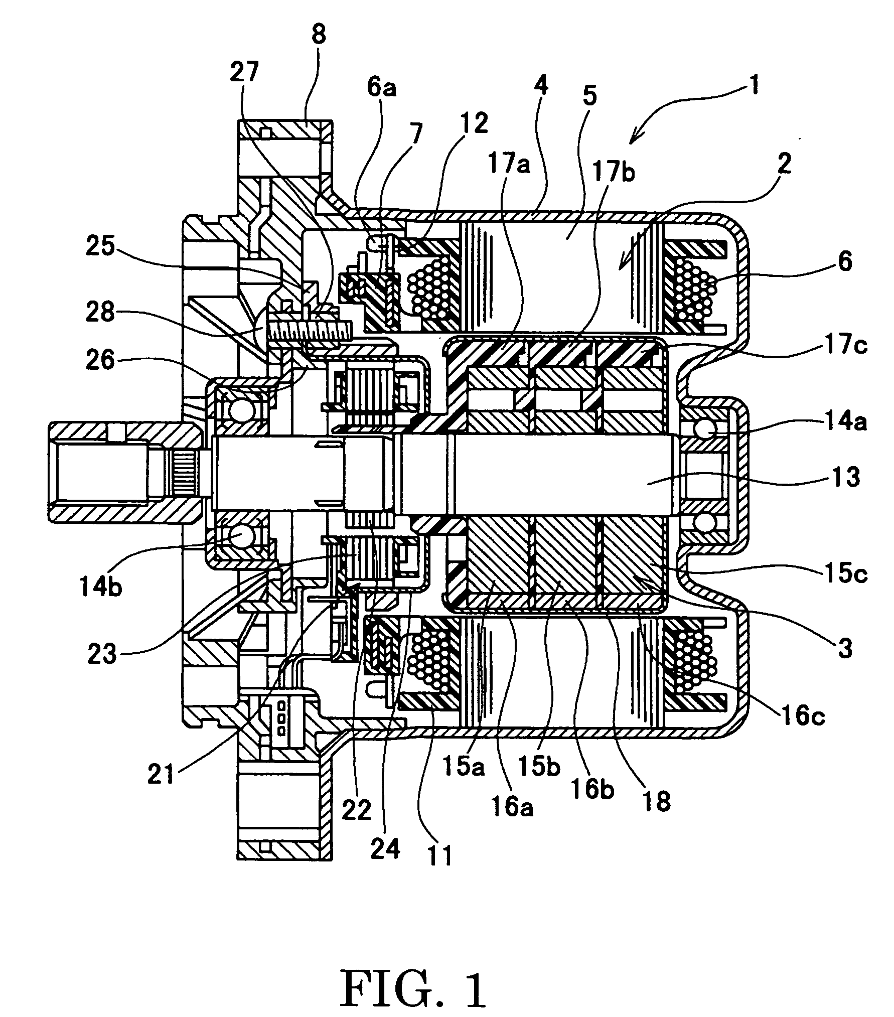
[0026]An embodiment of the present invention will be described in detail, with reference to the accompanying drawings. FIG. 1 is a sectional view of a brushless motor according to an embodiment of the present invention. As shown in FIG. 1, the brushless motor 1 (hereinafter referred to as “motor 1”) is an inner-rotor type that has a stator 2 and a rotor 3 arranged in the stator 2. For example, the motor 1 may be used as the power source of an electric power-steering (EPS) apparatus of column-assist type. The motor 1 can apply an auxiliary drive force to the steering shaft. The motor 1 is secured to a speed-reducing mechanism, which is in turn coupled to the steering shaft. The speed-reducing mechanism reduces the rotational speed of the motor 1 and transmits the rotation to the steering shaft.

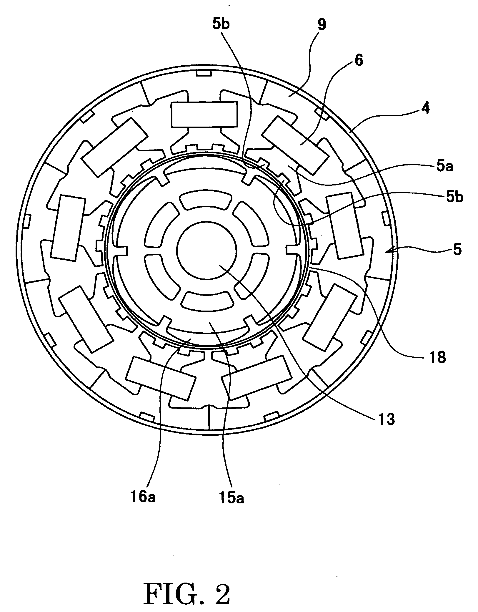
[0027]The stator 2 includes a case 4, a stator core 5, stator coils 6, and a bus-bar unit (terminal unit) 7. The stator coils 6 (hereinafter called “coils 6”) are wound around the stator core 5...


PUM


Abstract

In a brushless motor including a rotor having 2n poles and a stator having 3n slots, segment magnets arranged, in three columns, in the axial direction, thus constituting rotor poles. The segment magnets of adjacent columns, which are identical in polarity, are displaced in the circumferential direction, thus forming a three-stage step-skew structure. The skew angle θskew of each segment magnet is set to an electrical angle of 60° to 75°. The center angle of θm of each segment magnet is set to 46.8° to 52.7°.

Description

BACKGROUND OF THE INVENTION[0001]1. Field of the Invention[0002]The present invention relates to a brushless motor that has a skew structure. More particularly, the invention relates to a brushless motor of having a step-skew structure by means of segment magnets.[0003]2. Related Art Statement[0004]Hitherto known, as means for reducing cogging torque and torque ripple, is the skew structure in which the rotor poles or the like are inclined to the axis direction. In most brushless motors of skew structure, ring magnets are used as pole magnets. In any motor using ring magnets, the magnets are skew-magnetized in order to reduce cogging torque and torque ripple.[0005]In brushless motors designed for use in electric power steering apparatuses, the segment magnets that can be magnetized at high flux density are increasingly used as rotor magnet, thereby to meet the demand that the motors should be smaller and should yet achieve a large output. However, the segment magnets (right-angled m...

Claims


Application Information

Patent Timeline
Patent Type & Authority Applications(United States)
IPC IPC(8): H02K1/27
CPCH02K1/278H02K2213/03H02K2201/06H02K29/03
Inventor OKUBO, MASAYUKIKAWAMURA, MIKIO
Owner MITSUBA CORP
Why Eureka
Try Eureka