
Celestial body observation device

a technology of celestial bodies and observation devices, which is applied in the field of celestial body observation devices, can solve the problems of difficult comparison, difficult observation of celestial bodies in the sky,

Inactive Publication Date: 2009-09-10
CASIO COMPUTER CO LTD
View PDF9 Cites 31 Cited by
  • Summary
  • Abstract
  • Description
  • Claims
  • Application Information

AI Technical Summary

Benefits of technology

The present invention is a device that allows easy observation of celestial bodies in the sky. It includes a camera, a database with information on the position of the body, and a system to compare image data with the database and determine which body is being observed. The device generates complex image data that displays the body's information on top of the image. The technical effect of this invention is to provide an easy and convenient way to observe and identify celestial bodies.

Problems solved by technology

The resultant problem is that the comparison is sometimes difficult due to the state of the celestial body or a view line has to be moved between the sky and the screen to make the comparison and, therefore, specifying a celestial body positioned in the sky is not easy for the observer.

Method used


Image

  • Celestial body observation device
  • Celestial body observation device
  • Celestial body observation device

Examples


first embodiment

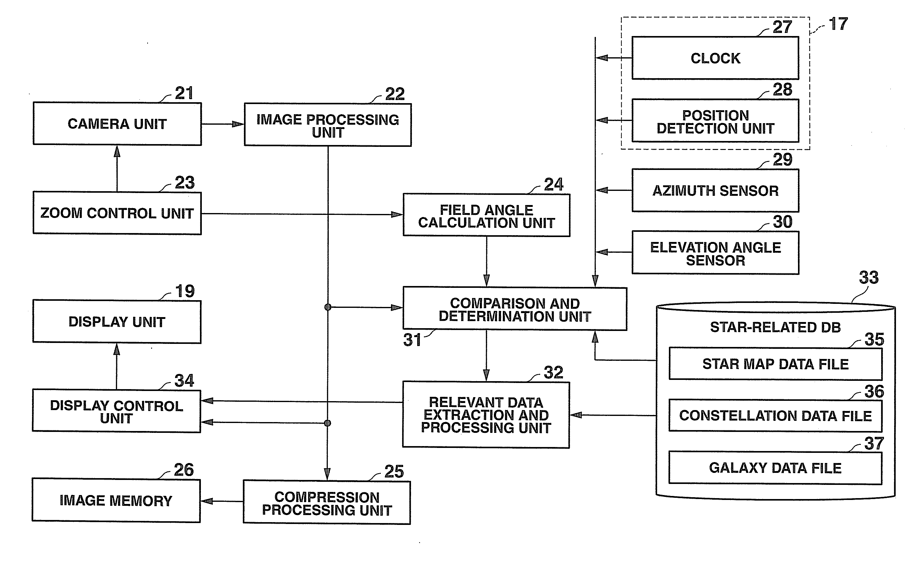
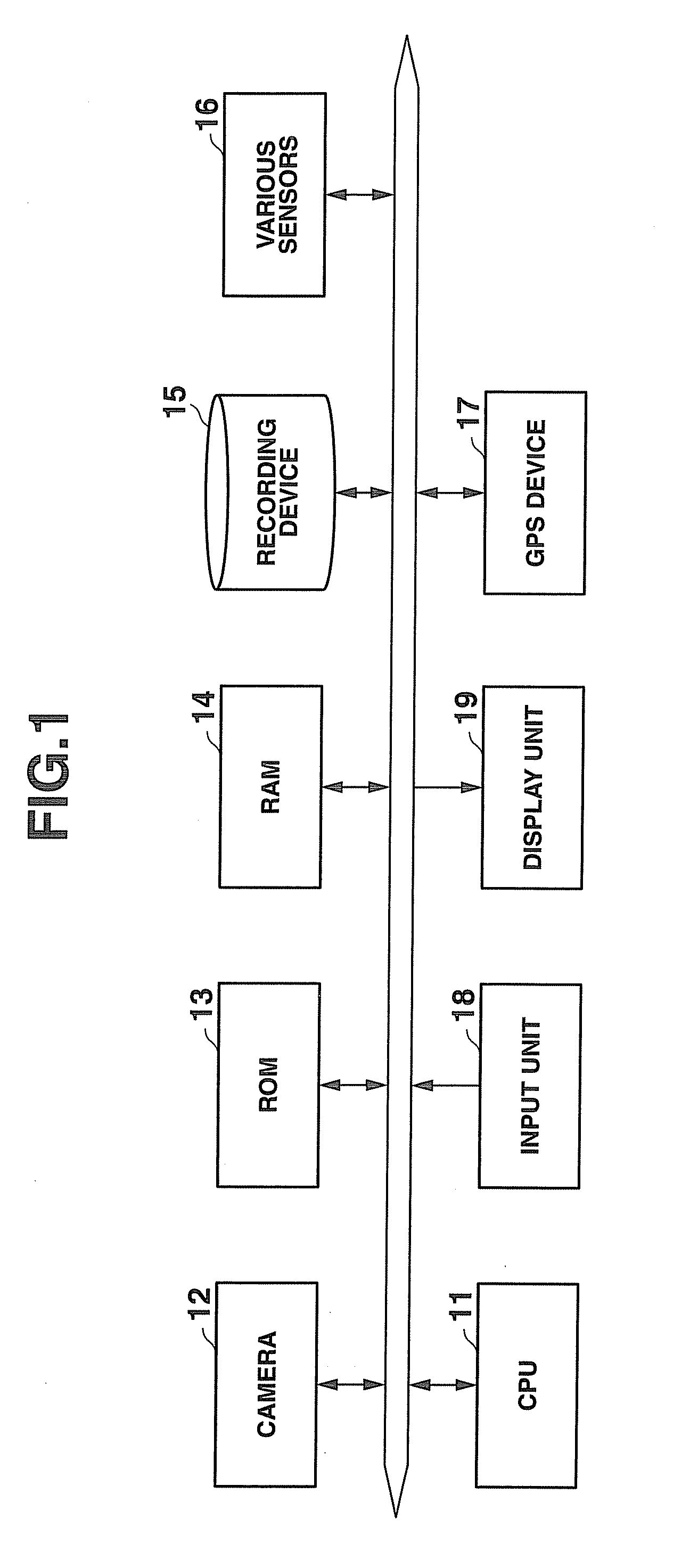
[0028]An embodiment of the present invention will be described below with reference to the appended drawings. FIG. 1 is a block diagram illustrating a configuration of a celestial body observation device of the present invention. The celestial body observation device of the present embodiment is in the form of, for example, a digital camera. As shown in FIG. 1, the celestial body observation device has a CPU 11, a camera 12, a ROM 13, a RAM 14, a recording device 15, various sensors 16, a GPS device 17, an input unit 18, and a display unit 19. In the present description celestial bodies include fixed stars and planets, and the fixed stars will be simply referred to as “stars”.

[0029]The CPU 11 controls pick-up with the camera 12, zooming, etc. according to a program and also executes processing of various types such as acquisition of information relating to celestial bodies including fixed stars (stars) and planets in the sky according to the information from the sensors 16 or GPS 17...

second embodiment

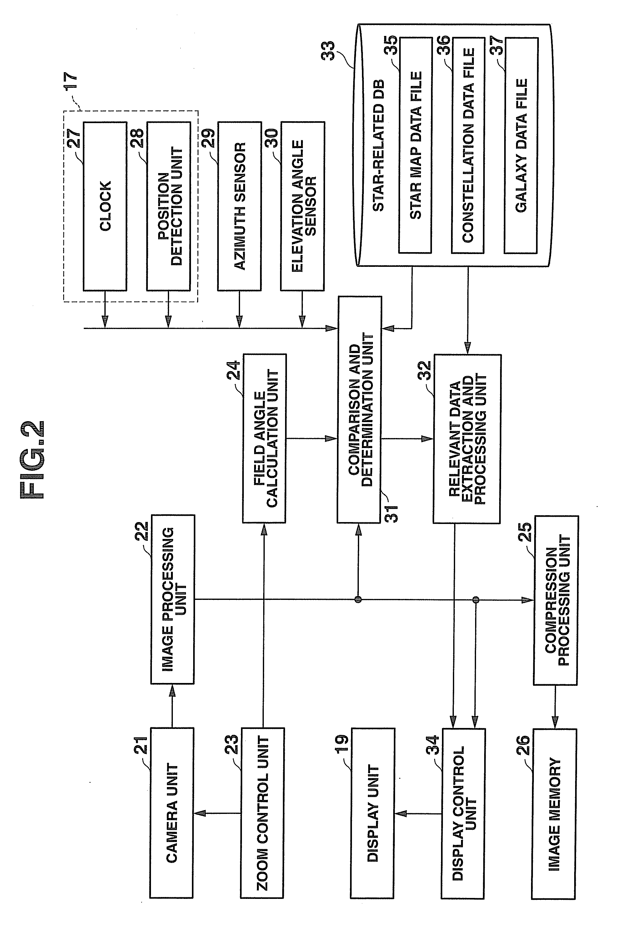
[0057]In the celestial body observation device of the second embodiment, processing is also executed according to flowchart shown in FIG. 3. Thus, where a preview instruction is received from the observer (step 301), the image processing unit 22 acquires image data from the camera unit 21 and outputs the acquired image data to the display control unit 34. As a result, image data picked up by the lens of the camera unit 21 are displayed as a preview image on the screen of the display unit 19 (step 302). The observer can display an image of the desired field angle on the screen of the display unit 19 by operating a zoom switch (not shown in the figure) of the input unit 18. In this case, the zoom control unit 23 controls the lens of the camera unit 21 correspondingly to the operation of the zoom switch performed by the observer. The image processing unit 22 executes filtering processing of image data of the preview image (step 303). The filtering processing verifies the position and b...


PUM


Abstract

A celestial body observation device having a camera unit 21, a star-related database 33 including a star map data file 35 that stores star map data having positions of stars and display information including names of the stars, a comparison and determination unit 31 that compares a pixel group contained in image data picked up by the camera unit 21 with star map data within a star map data file 24 and specifies a celestial body corresponding to the pixel group, and a display control unit 34 that acquires display information of star map data associated with the pixel group from the star map data file 35 on the basis of association between the pixel group specified by the comparison and determination unit 31 and the star and generates complex image data in which the display information is superimposed on the image data.

Description

CROSS-REFERENCE TO RELATED APPLICATIONS[0001]This application is based upon and claims the benefit of priority from the prior Japanese Patent Application No. 2008-54691, filed Mar. 5, 2008, the entire contents of which are incorporated herein by reference.BACKGROUND OF THE INVENTION[0002]1. Field of the Invention[0003]The present invention relates to a celestial body observation device that provides various types of information to an observer during observations of a celestial body.[0004]2. Description of the Related Art[0005]Measuring the present position or accurate time by employing a GPS (Global Positioning System) is employed in many fields, for example, in car navigation. Because the present position can be measured, that is, positioned, with a GPS, a device has been suggested for displaying a star map that has to be visible from this position.[0006]JP-A-2002-328624 suggests providing display means at an inner surface of a ceiling in an automobile cabin and displaying a star m...

Claims


Application Information

Patent Timeline
Patent Type & Authority Applications(United States)
IPC IPC(8): H04N7/18G01S1/00G01S19/51
CPCH04N7/183G09B27/04
Inventor HIROTANI, TAKAYUKI
Owner CASIO COMPUTER CO LTD
Learn More