System and Method For Independent Image Sensor Parameter Control in Regions of Interest

a technology of independent image sensor and parameter control, which is applied in the field of image quality improvement in a region of interest, can solve the problems of affecting the cost effectiveness of camera systems, affecting the image quality of cameras,

Active Publication Date: 2009-09-10
OMNIVISION TECH INC
View PDF10 Cites 120 Cited by
  • Summary
  • Abstract
  • Description
  • Claims
  • Application Information

AI Technical Summary

Benefits of technology

[0006]An image sensor includes an array of pixels. The image sensor is designed to permit image sensor parameters to be independently set in two or more different

Problems solved by technology

However, radar based automotive systems can be expensive, with some radar systems costing several thousand dollars.
However, there is substantial vibration and shock in automobiles, which makes it difficult to integrate a zoom lens with a forward looking camera system in a cost effective manner.
Consequently, in conventional forward looking automobile camera systems the resolution may be too poor to effectively support many desirable applications.
Additionally, prior art forward looki

Method used


Image

  • System and Method For Independent Image Sensor Parameter Control in Regions of Interest
  • System and Method For Independent Image Sensor Parameter Control in Regions of Interest
  • System and Method For Independent Image Sensor Parameter Control in Regions of Interest

Examples


Embodiment Construction

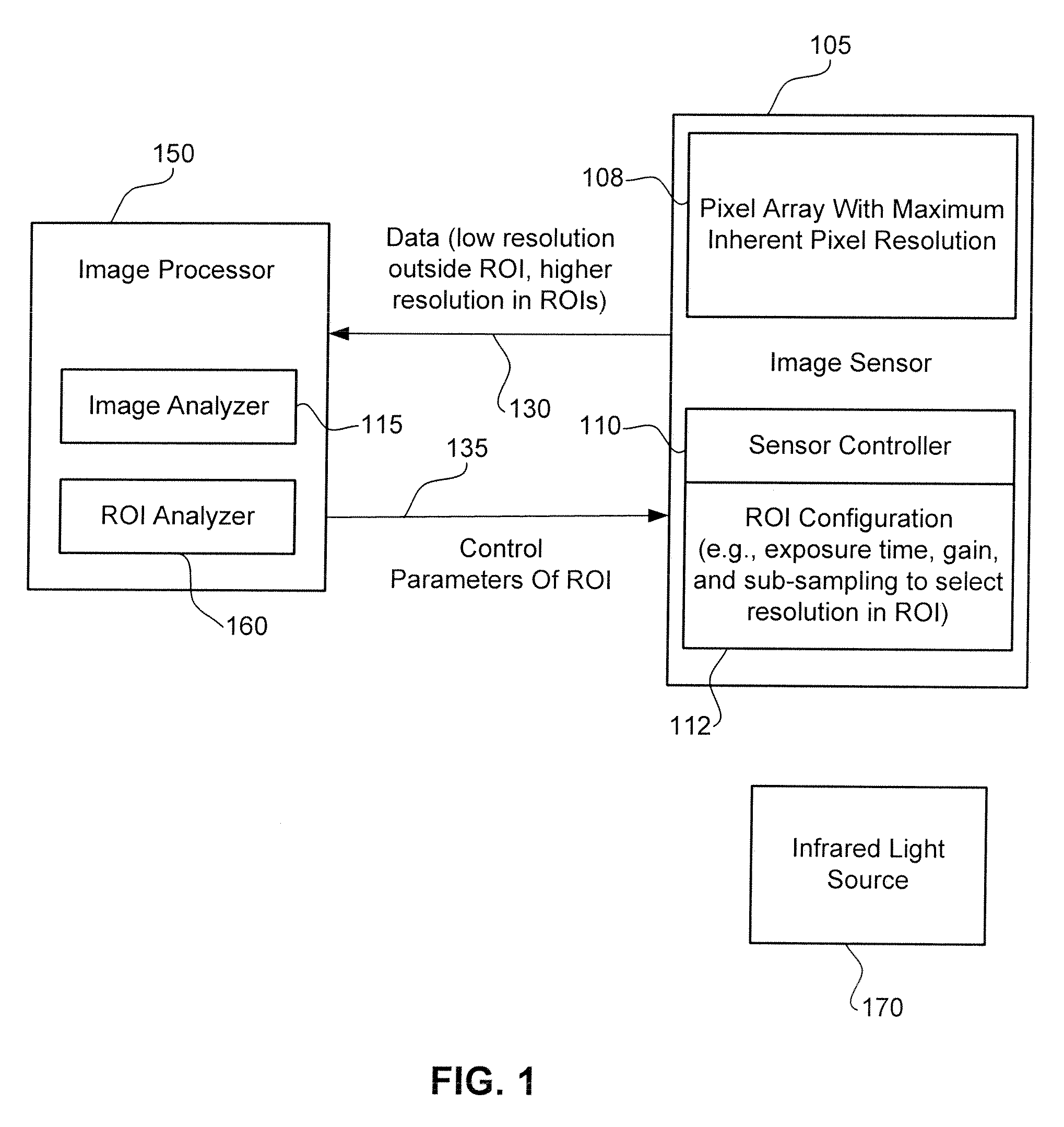
[0018]FIG. 1 illustrates an exemplary image sensing system 100 in accordance with one embodiment of the present invention. An image sensor 105 includes a pixel array 108 with a maximum inherent pixel resolution based on a total maximum number of pixels. As an illustrative example, image sensor 105 may be a CMOS image sensor having a pixel resolution of 4-to-10M pixels or higher when operated in a full resolution mode. An exemplary frame rate for automotive applications is the range of 30-60 frames per second. However, image sensor 105 also supports sub-sampling, i.e., a mode of operation in which data is collected for only a pre-selected fraction of the pixels with, for example one pixel representing a larger group of pixels. As an illustrative example, the sub-sampling frequency may be selected such that the effective resolution is reduced by a factor of 4 to 10.

[0019]Operating image sensor 105 at sub-sampling frequencies reduces the power consumption and heat generation of image s...


PUM


Abstract

An image sensing systems supports independently setting sensor parameters in two or more different regions of interest. In one implementation resolution, exposure time, and gain are independently selectable in each region of interest. Independently setting exposure time and gain in different regions of interest improves image recognition when there are large difference in the illumination of objects within an image. Independently setting resolution permits the resolution to be selectively increased in regions of interest requiring high resolution in order to reduce the pixel data bandwidth and processing requirements.

Description

FIELD OF THE INVENTION[0001]The present invention is generally related to techniques to improve image quality in a region of interest. More particularly, the present invention is directed to improving image quality in multiple regions of interest.BACKGROUND OF THE INVENTION[0002]There is increasing interest in improving the safety of automobiles using on-board safety systems. One approach in the prior art is the use of radar based collision avoidance systems. For example, a radar based collision avoidance system can provide information on the distance between cars even when there is poor visibility. However, radar based automotive systems can be expensive, with some radar systems costing several thousand dollars.[0003]Image sensors, such as Complementary Metal Oxide Semiconductor (CMOS) image sensors, detect light in the visible and / or infrared wavelengths. Consequently image sensors can also be utilized to improve automobile safety. Conventionally, image sensors have been widely us...

Claims


Application Information

Patent Timeline
IPC IPC(8): H04N5/235H04N5/228
CPCH04N5/345H04N5/347H04N5/3454G03B7/003H04N25/44H04N25/443H04N25/46
Inventor MORIN, JEFFREY L.
Owner OMNIVISION TECH INC
Why Eureka
Try Eureka