
Method and apparatus for monitoring angle random walk of a fiber optic gyroscope

Active Publication Date: 2009-09-10
HONEYWELL INT INC
View PDF2 Cites 7 Cited by
  • Summary
  • Abstract
  • Description
  • Claims
  • Application Information

AI Technical Summary

Benefits of technology

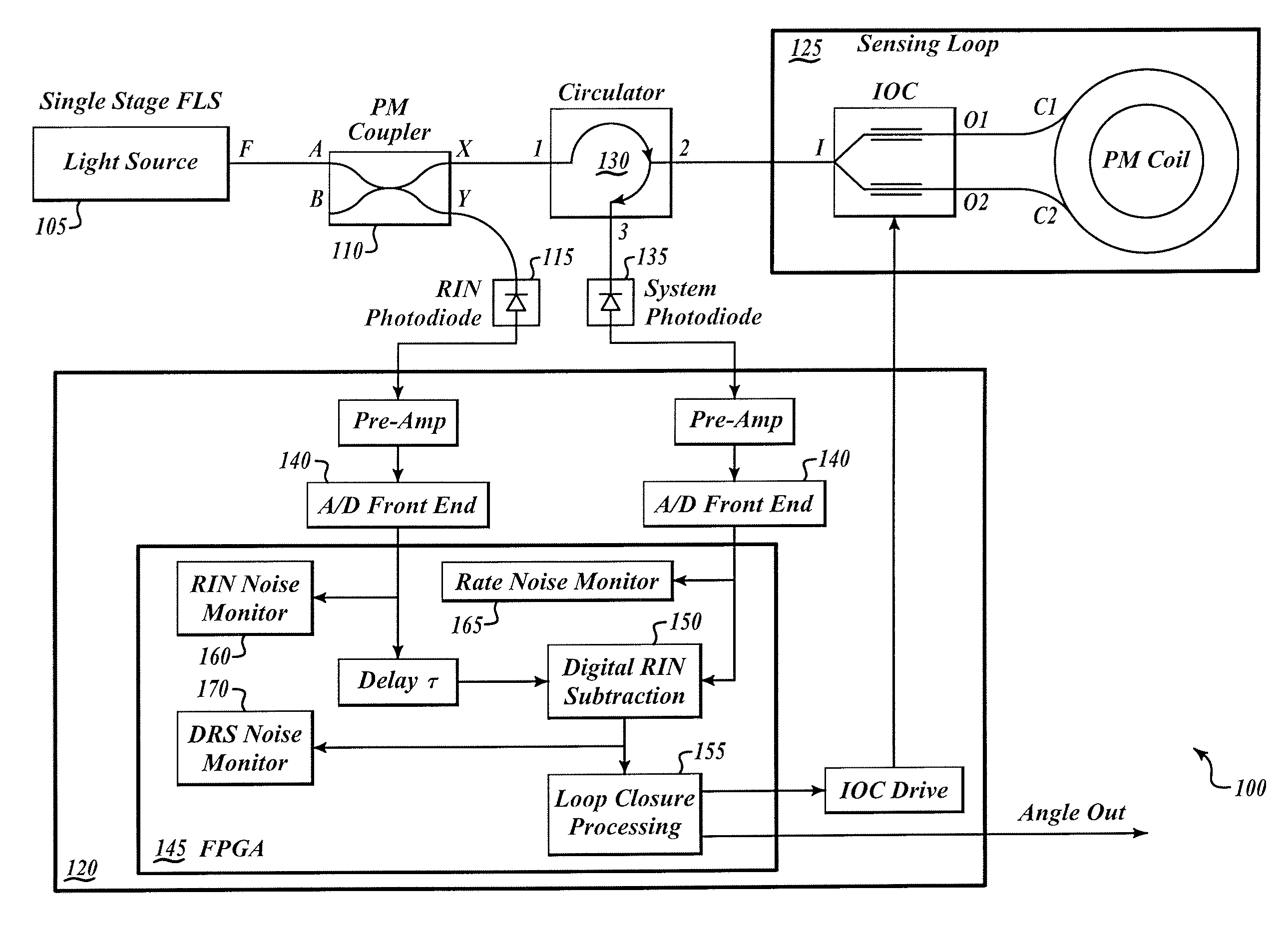
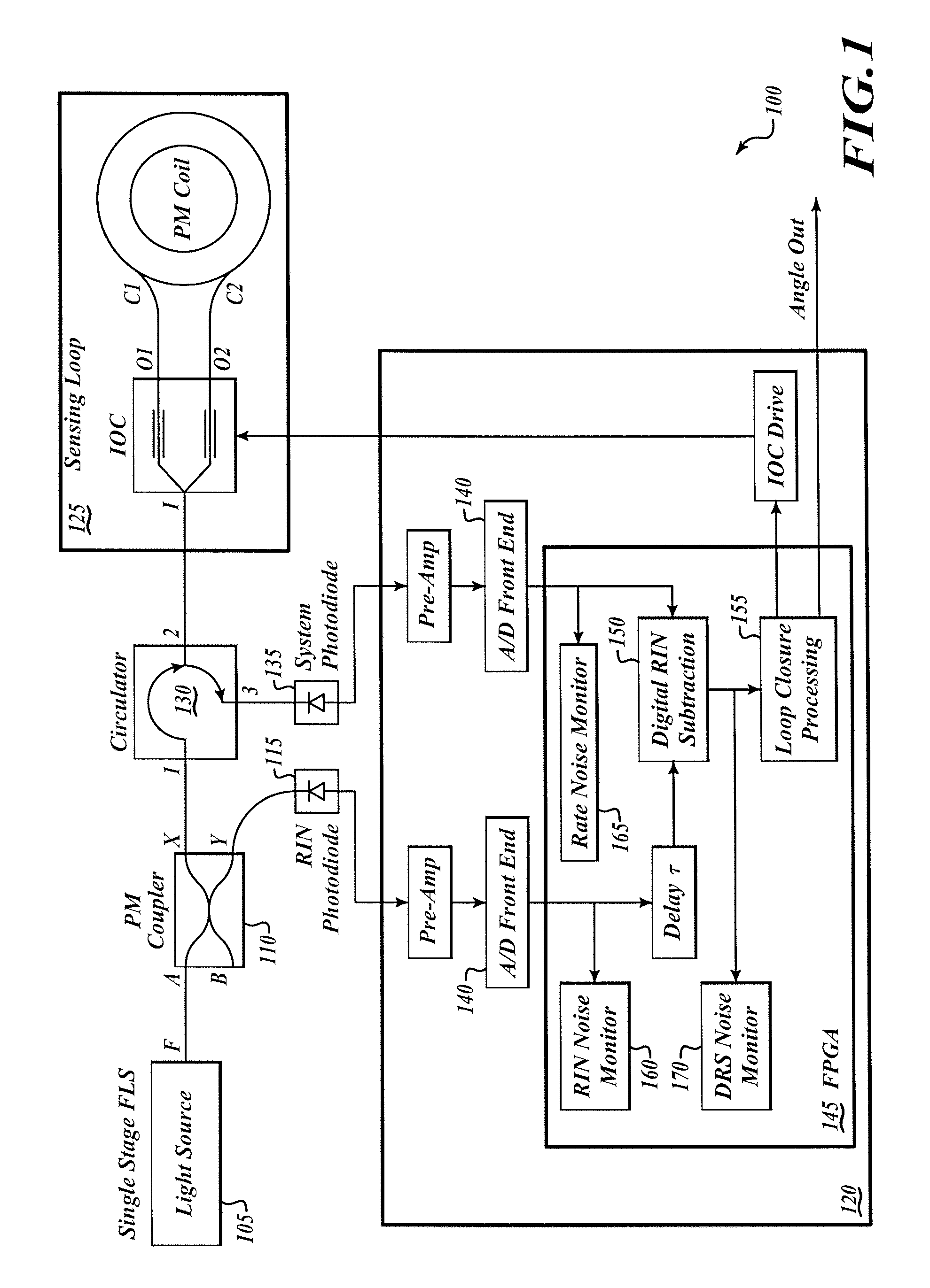
[0004]In an embodiment, a system for determining a level of ARW associated with a FOG includes first and second photodiodes. The first photodiode is configured to receive a first light signal from a light source associated with the FOG. The second photodiode is configured to receive a second light signal from a fiber optic coil associated with the FOG. First and second analog-to-digital converters (ADCs) are operable to respectively convert the first and second light signals into corresponding respective first and second digital signals. A digital relative-intensity-noise (RIN) subtraction element is configured to receive the first and second digital signals and output a third signal based on the first and second digital signals, which can serve to reduce noise in an IFOG output. An electronic device is configured to determine a first noise level associated with the third signal, and determine the ARW level from the first noise level.

Problems solved by technology

When the beams exit the fiber they are combined, and the phase shift introduced due to the Sagnac effect causes the beams to interfere, resulting in a combined beam whose intensity depends on the angular velocity.
ARW is random measurement noise that ultimately limits the accuracy of the FOG and leads to navigation errors.
A gyroscope's ARW can be specified by the manufacturer, but it can degrade over time due to faults, aging, or other causes.

Method used


Image

  • Method and apparatus for monitoring angle random walk of a fiber optic gyroscope
  • Method and apparatus for monitoring angle random walk of a fiber optic gyroscope
  • Method and apparatus for monitoring angle random walk of a fiber optic gyroscope

Examples


Embodiment Construction

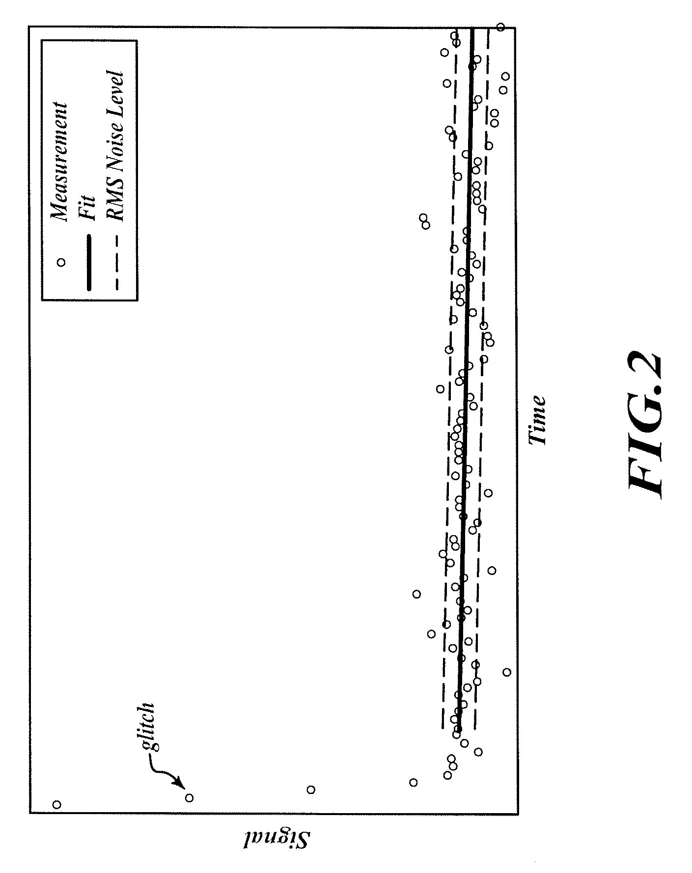
[0009]As will be more fully described hereinafter, a system and method according to an embodiment, and as best illustrated with reference to FIG. 1, uses high-speed photodiode data collected during ½ of a bias modulation of a FOG. This method includes measuring the noise on the data using a noise estimation technique such as, for example, root-mean-square (RMS), avg(abs( )), or peak-to-peak, and uses such noise as a proxy for ARW. If one assumes the noise to be “white noise,” then a proportionality relationship exists and is given by the relative bandwidths of the noise monitor versus the output band.

[0010]An alternative system and method according to an embodiment, and as best illustrated with reference to FIG. 3, uses lower speed data at the output of a demodulator. The demodulated signal may be low-pass filtered and possibly downsampled to produce the FOG output. The RMS noise energy removed by the filter may be treated as a proxy for ARW. If one assumes the noise to be “white no...


PUM


Abstract

A system for determining a level of angle random walk (ARW) associated with a fiber optic gyroscope (FOG) includes first and second photodiodes. The first photodiode is configured to receive a first light signal from a light source associated with the FOG. The second photodiode is configured to receive a second light signal from a fiber optic coil associated with the FOG. First and second analog-to-digital converters (ADCs) are operable to respectively convert the first and second light signals into corresponding respective first and second digital signals. A digital relative-intensity-noise (RIN) subtraction element is configured to receive the first and second digital signals and output a third signal based on the first and second digital signals. An electronic device is configured to determine a first noise level associated with the third signal, and determine the ARW level from the first noise level.

Description

STATEMENT REGARDING FEDERALLY SPONSORED RESEARCH OR DEVELOPMENT[0001]The present invention was made with support from the United States Government under Grant number N00030-05-C-0063 awarded by the United States Navy. The United States Government has certain rights in the invention.BACKGROUND OF THE INVENTION[0002]A fiber optic gyroscope (FOG) uses the interference of light to measure angular velocity. A FOG consists of a large coil of optical fiber. To measure rotation, two light beams are fired into the coil in opposite directions. If the sensor is undergoing a rotation then the beam traveling in the direction of rotation will experience a longer path to the other end of the fiber than the beam traveling against the rotation. This is known as the Sagnac effect. When the beams exit the fiber they are combined, and the phase shift introduced due to the Sagnac effect causes the beams to interfere, resulting in a combined beam whose intensity depends on the angular velocity.[0003]Angl...

Claims


Application Information

Patent Timeline
IPC IPC(8): G01C19/66
CPCG01C19/72
Inventor BUSCH, DARRYLSTRANDJORD, LEETARLETON, NORMAN
Owner HONEYWELL INT INC
Learn More