Method of creating correction table for head position control, head position control method, and disk device

a correction table and head position technology, applied in the field of creating correction tables for head position control, head position control methods, disk devices, etc., can solve the problems of deteriorating positioning accuracy, difficult measurement and correction, and inability to accurately record servo signals concentrically during stw, so as to reduce computation load, shorten time, and meet specifications

Inactive Publication Date: 2009-09-10
KK TOSHIBA
View PDF12 Cites 3 Cited by
  • Summary
  • Abstract
  • Description
  • Claims
  • Application Information

AI Technical Summary

Benefits of technology

[0044]With the foregoing in view, it is an object of the present invention to provide a method of creating a correction table that decreases the computation load and satisfies the specifications of positioning accuracy in a shorter time when RRO and URRO, that is one of the correction values for the correction table, is calculated, and a head positioning control method and a disk device thereof.
[0045]It is another object of the present invention to provide a method for creating a correction table which decreases computing load and satisfies the specifications of positioning accuracy in a shorter time, even if a computation equivalent to DFT / inverse DFT is performed, when RRO or URRO, this is one of the correction values for the correction table, is calculated, and a head positioning control method and a disk device thereof.
[0046]It is still another object of the present invention to provide a correction table creation method for creating a correction table in a shorter time even if the correction values of many tracks are calculated when RRO or URRO, that is one of the correction values for the correction table, is calculated, and a head positioning control method and a disk device thereof.

Problems solved by technology

The position signal, however, includes noise, which deteriorates the positioning accuracy.
For the component not synchronizing with rotation, on the other hand, measurement and correction are difficult.
The first cause is that the servo signals are not accurately recorded concentrically during STW.
As long as the servo signals are mechanically recorded, mechanical, electrical and magnetic noises during recording are unavoidable.
Therefore to accurately record the servo signals concentrically during STW is extremely difficult.
If RRO occurs, the positioning accuracy of the head deteriorates, which causes problems with reading and regenerating data.
This means that even if RRO can be suppressed, the same suppression rate cannot always be implemented for RPE.
As described above, the calculation amount for calculating RRO and URRO is large, the program size used for processing is also large, and load on the MCU is high.
This makes the measurement time of the RPE required for satisfying the specifications of positioning accuracy, that is the time required for creating a correction table in the manufacturing steps, long, when correction values are measured in the manufacturing steps of a disk device, which is not appropriate for mass manufacturing of disk devices.

Method used


Image

  • Method of creating correction table for head position control, head position control method, and disk device
  • Method of creating correction table for head position control, head position control method, and disk device
  • Method of creating correction table for head position control, head position control method, and disk device

Examples


first embodiment

of RRO Correction Table Creation Method

[0111]FIG. 7 is a functional block diagram depicting the first embodiment of the RRO correction table creation method. FIG. 7 shows a block diagram in the case of calculating a filter function F(x) and creating the correction table by a single disk device. FIG. 8 is a flow chart depicting the filter function F(x) calculation processing in FIG. 7, FIG. 9 is a flow chart depicting the RRO table creation processing using the filter function F(x) in FIG. 8, FIG. 10 is a graph depicting the filter function F(x) created in FIG. 8, and FIG. 11 shows the F(x) table 23 in FIG. 7.

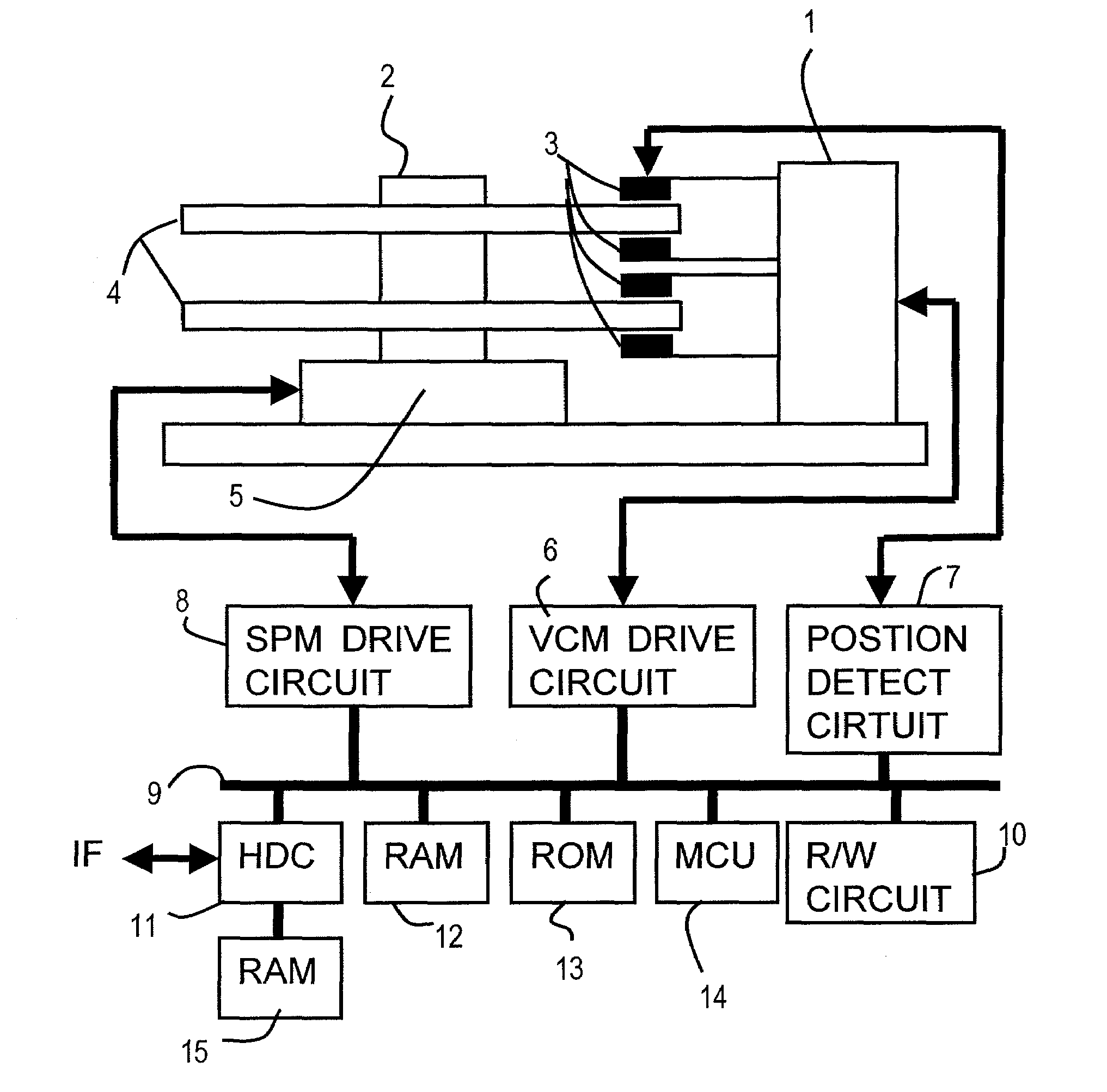
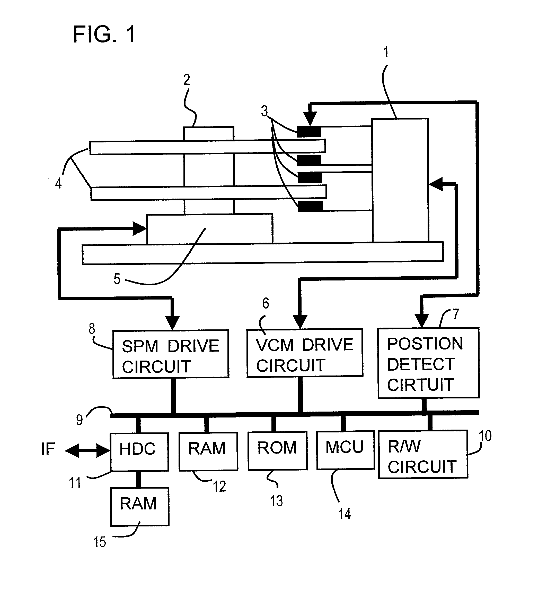
[0112]In FIG. 7, composing elements the same as those in FIG. 6 are denoted with the same reference numerals. In other words, the error ‘e’ between the target position ‘r’ and the current (observing) position ‘y’ is determined by the computation block 22, and the controller 20 performs control computation, calculates the control amount and drives the VCM 1, that is the plant 21....

second embodiment

of RRO Correction Table Creation Method

[0152]FIG. 14 is a graph depicting the filter function F(x) of the second embodiment of the present invention, FIG. 15 is a flow chart depicting the correction table creation processing of the second embodiment of the present invention, and FIG. 16 are graphics depicting the relationship of the frequency characteristics according to the second embodiment and actual sensitivity functions.

[0153]In the case of the above mentioned filter function F(x) for one rotation in FIG. 10, the values at both ends in FIG. 10 are close to “0”. So F(x) at both ends for one rotation in the X direction are not used for calculation, but are removed, as shown in FIG. 14, and only the center part is used for calculation to decrease calculation amount.

[0154]The correction table creation processing will be described in details with reference to FIG. 15.

[0155](S50) Just like step S40 in FIG. 13, the RRO correction value of each sector q of the correction table 29, that...

third embodiment

of RRO Correction Table

[0166]FIG. 17 is a block diagram depicting the third embodiment of the head positioning control system of the present invention, FIG. 18 is a diagram depicting the residual RRO for creating RroTable, FIG. 19 is a flow chart depicting the RRO gain optimum value calculation processing using the residual RRO, FIG. 20 is a flow chart depicting RRO measurement processing in FIG. 19, FIG. 21 is a flow chart depicting NRRO measurement processing in FIG. 19, FIG. 22 is a flow chart depicting F(x) computation processing of the F(x) computation block in FIG. 17, FIG. 23 is a graph depicting the filter function F(x) by the processing in FIG. 22, and FIG. 24 is a flow chart depicting the RPE acquisition and waveform calculation processing in FIG. 17.

[0167]FIG. 17 is also a block diagram when the optimum value calculation and correction table creation are performed by a single disk device, and composing elements the same as FIG. 6 and FIG. 7 are denoted with the same refer...


PUM

PropertyMeasurementUnit
widthaaaaaaaaaa
frequencyaaaaaaaaaa
frequencyaaaaaaaaaa

Abstract

A head position control method controls the position of a head by correcting components synchronizing rotation of a disk based on the head control amount. A correction signal for components synchronizing rotation is generated by using a filter function. The filter function that integrates the sine and cosine terms of DFT and inverse DFT and forms multiply of the complex values a(m) and b(m) and sine and cosine for frequency conversion, is measured in advance. The complex values are the m degree of RRO frequencies having frequency characteristics to be multiplied (1+C(z) P(z)) or −(1+C(z) P(z) / P(z)).

Description

[0001]This application is a divisional of U.S. application Ser. No. 11 / 086,520, filed Mar. 22, 2005.CROSS-REFERENCE TO RELATED APPLICATIONS[0002]This application is based upon and claims the benefit of priority from the prior Japanese Patent Application No. 2004-325451, filed on Nov. 9, 2004, the entire contents of which are incorporated herein by reference.BACKGROUND OF THE INVENTION[0003]1. Field of the Invention[0004]The present invention relates to a correction table creation method of head position control for a disk device which controls the position of a head to a rotating disk, for performing reading and / or writing information from / to the disk, and the head position control method, and the disk device thereof, and more particularly to a correction table creation method of head position control for correcting the rotation synchronization component of the disk and position signal, and the head position control method and the disk device thereof.[0005]2. Description of the Rela...

Claims


Application Information

Patent Timeline
Patent Type & Authority Applications(United States)
IPC IPC(8): G11B21/02
CPCG11B5/59627G11B19/06G11B21/08
Inventor TAKAISHI, KAZUHIKO
Owner KK TOSHIBA
Why Eureka
Try Eureka