
Method and apparatus for generating high power visible and near-visible laser light

a laser light and visible and near-visible technology, applied in the direction of semiconductor lasers, laser details, basic electric elements, etc., can solve the problems of generating power levels above 1 watt at arbitrary wavelengths, reducing the efficiency and reliability of laser light generation, and limiting the available output power to the sub-watt level, etc., to achieve efficient and reliable output beams and high brightness

Active Publication Date: 2009-09-10
RAM PHOTONICS IND LLC
View PDF0 Cites 65 Cited by
  • Summary
  • Abstract
  • Description
  • Claims
  • Application Information

AI Technical Summary

Benefits of technology

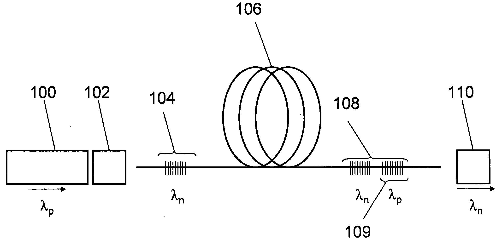
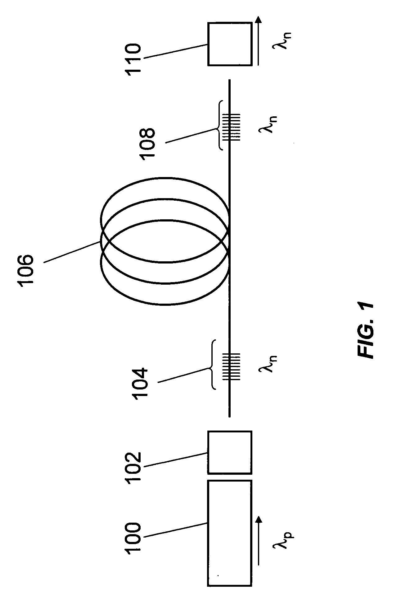
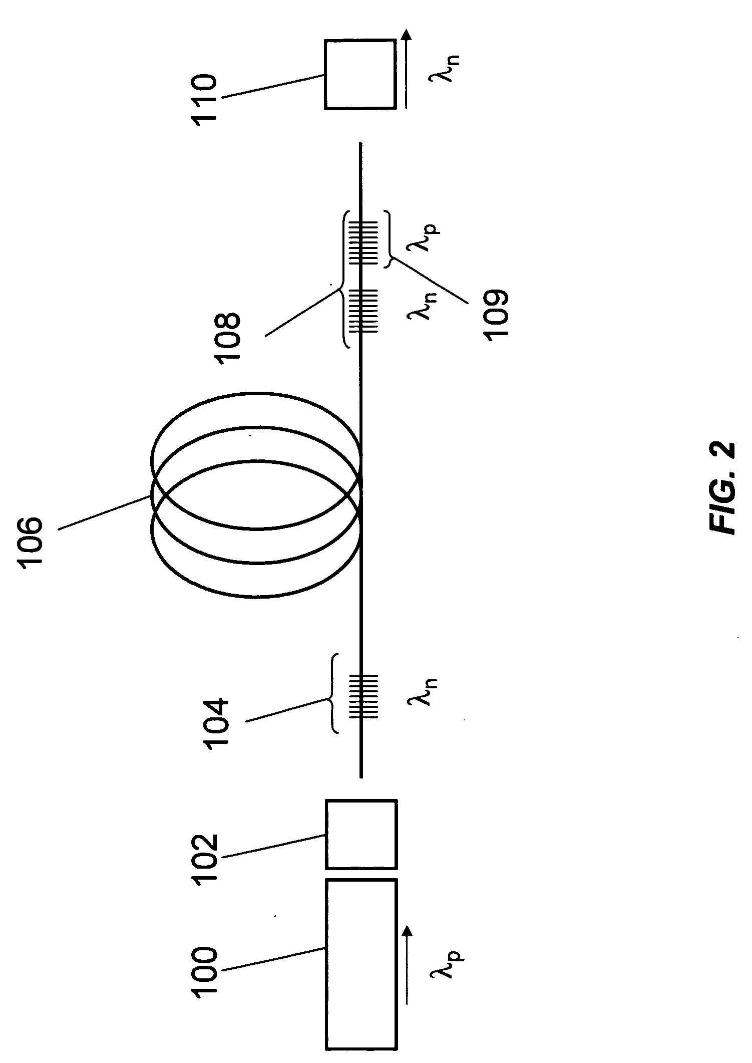
"The present invention provides a system that includes a multimode fiber Raman laser that can spatially clean up and simultaneously frequency convert, via the Stimulated Raman Scattering (SRS) process, the low-brightness emission of modern high-powered diode lasers into high-brightness light. This high brightness emission is suitable for efficient nonlinear frequency conversion, via parametric processes, to produce visible wavelengths at high efficiency and high power compared to existing technologies. The apparatus can be applied to other applications as well."

Problems solved by technology

Generating power levels above 1 watt at arbitrary wavelengths has proven to be challenging, especially with good beam quality (M2˜1).
GaN-based diode lasers can access visible and near-visible wavelengths, but the available output power is generally limited to the sub-watt level.
Various gas and liquid (i.e., dye) lasers have similar performance, but are also plagued with efficiency and reliability issues, as well as significant system complexity.
Despite their high reliability, solid-state and fiber lasers cannot readily access such wavelengths.
Not only are such systems highly complicated to construct and maintain, but the parametric processes are not highly efficient.
Therefore, cascading parametric processes often results in lower output power or places high requirements on the original pump laser input power and beam quality.

Method used


Image

  • Method and apparatus for generating high power visible and near-visible laser light
  • Method and apparatus for generating high power visible and near-visible laser light
  • Method and apparatus for generating high power visible and near-visible laser light

Examples


Embodiment Construction

[0021]The first fiber-based Raman lasers were demonstrated in the late 1970's. In 1992 Chiang used nanosecond pulses from a dye laser to observe beam cleanup via SRS in multimode optical fiber. In 1999 Rodgers et al demonstrated coherent beam combining and cleanup using stimulated Brillouin scattering in multimode optical fiber. This work was followed up two years later combining incoherent beams.

[0022]Significant advances in rare-earth-doped fiber lasers began at the turn of the millennium. These advances were driven by improvements in diode pump lasers, fiber processing and device design. Substantial effort and innovation have been invested in maintaining single-mode operation in these high-power devices. The bias towards single-mode devices has been maintained as high-power Raman lasers have begun being sought.

[0023]In 2002 Dianov published a review article, “Advances in Raman Fibers” and discussed only single-mode devices. In the above referenced articles, fiber Raman lasers are...


PUM


Abstract

A multimode-fiber Raman laser includes a pump source configured to provide optical radiation centered at a pump wavelength and characterized by a spectral bandwidth greater than 100 MHz and an oscillator resonant at an emission wavelength greater than the pump wavelength. The oscillator includes an input coupler optically aligned with the pump source and a multimode optical fiber optically coupled to the input coupler. The multimode optical fiber includes an input section having a fiber Bragg grating, an intracavity section of a predetermined length optically coupled to the input section, and an output section having a fiber Bragg grating. The oscillator also includes an output coupler optically coupled to the multimode optical fiber and configured to provide a laser output at the emission wavelength.

Description

CROSS-REFERENCES TO RELATED APPLICATIONS[0001]This present application claims priority to U.S. Provisional Patent Application No. 61 / 035,315, filed on Mar. 10, 2008, the disclosure of which is hereby incorporated by reference in its entirety for all purposes.BACKGROUND OF THE INVENTION[0002]High-power light at visible and near visible wavelengths is highly desirable in many applications. In medical applications, specific wavelengths are utilized to affect specific tissues. In the display industry, large displays and projection systems utilize red, green, and blue colors to derive the full observable color spectrum. Yellow lasers (e.g., 589 nm) are particularly useful for guide-star applications in correcting atmospheric distortions in ground-based extra-terrestrial imaging.[0003]Generating power levels above 1 watt at arbitrary wavelengths has proven to be challenging, especially with good beam quality (M2˜1). GaN-based diode lasers can access visible and near-visible wavelengths, b...

Claims


Application Information

Patent Timeline
Patent Type & Authority Applications(United States)
IPC IPC(8): H01S3/30H01S5/00
CPCH01S3/06712H01S3/0675H01S3/302H01S3/09408H01S3/109H01S3/094011
Inventor MARCIANTE, JOHN R.RYAN, ANDREW T.
Owner RAM PHOTONICS IND LLC
Learn More