Method of object recognition in image data using combined edge magnitude and edge direction analysis techniques

a combined edge magnitude and edge direction analysis technology, applied in image analysis, image enhancement, instruments, etc., can solve the problems of corresponding increase in false alarm rate and detection level, and achieve positive detection, facilitate real-time operation, and quickly and correctly detect objects

Inactive Publication Date: 2009-09-10
LOCKHEED MARTIN CORP
View PDF9 Cites 51 Cited by
  • Summary
  • Abstract
  • Description
  • Claims
  • Application Information

AI Technical Summary

Benefits of technology

[0010]Also unlike other detection methods, the processing load is maintained at a moderate level as sensitivity and positive detection rates increase. While a sufficiently complex detection method may be capable of eventually correctly identifying every area of interest in an image, the inventive method facilitates real-time operation by enabling a computationally efficient approach to quickly and correctly detect objects and areas of interest in an image.
[0011]In a preferred embodiment of the inventive method, one of the goals is the extraction of target-like hotspots from a mid-wave infrared image while minimizing the extraction of hotspots that are false alarms. The target size parameters supplied as input data allow the inventive method to be tailored for specific environments such as maritime or open ground. It can be used to identify both known and unknown targets and target areas. This embodiment is intended as a target acquisition system for missile systems and other weapons systems.
[0012]In alternative embodiments, the goal may be the identification of large, dense objects in baggage passing through an x-ray scanner, the detection and tracking of vehicles using video monitoring, or identification of areas of interest on a PET scan. The inventive method can effectively be applied to any scenario where automated forms of object or area detection, tracking, or identification are required.
[0013]In a preferred embodiment of the inventive method, the infrared intensity image is used to create a thresholded magnitude and a

Problems solved by technology

As sensitivity is increased and detection parameters are more broadly construed, the level

Method used


Image

  • Method of object recognition in image data using combined edge magnitude and edge direction analysis techniques
  • Method of object recognition in image data using combined edge magnitude and edge direction analysis techniques
  • Method of object recognition in image data using combined edge magnitude and edge direction analysis techniques

Examples


Embodiment Construction

[0036]The following detailed description of the invention refers to the accompanying drawings. The same reference numbers in different drawings identify the same or similar elements. Also, the following detailed description does not limit the invention. Instead, the scope of the invention is defined by the appended claims and equivalents thereof.

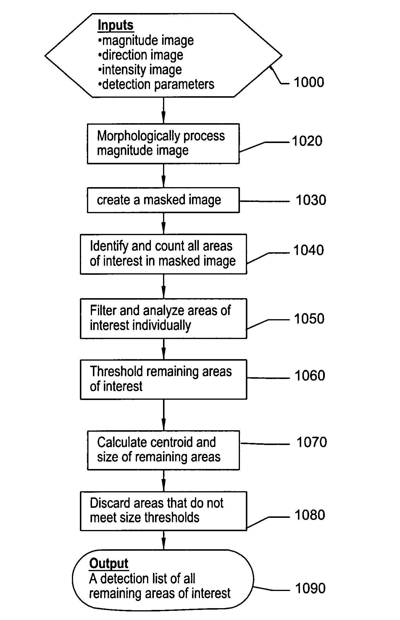
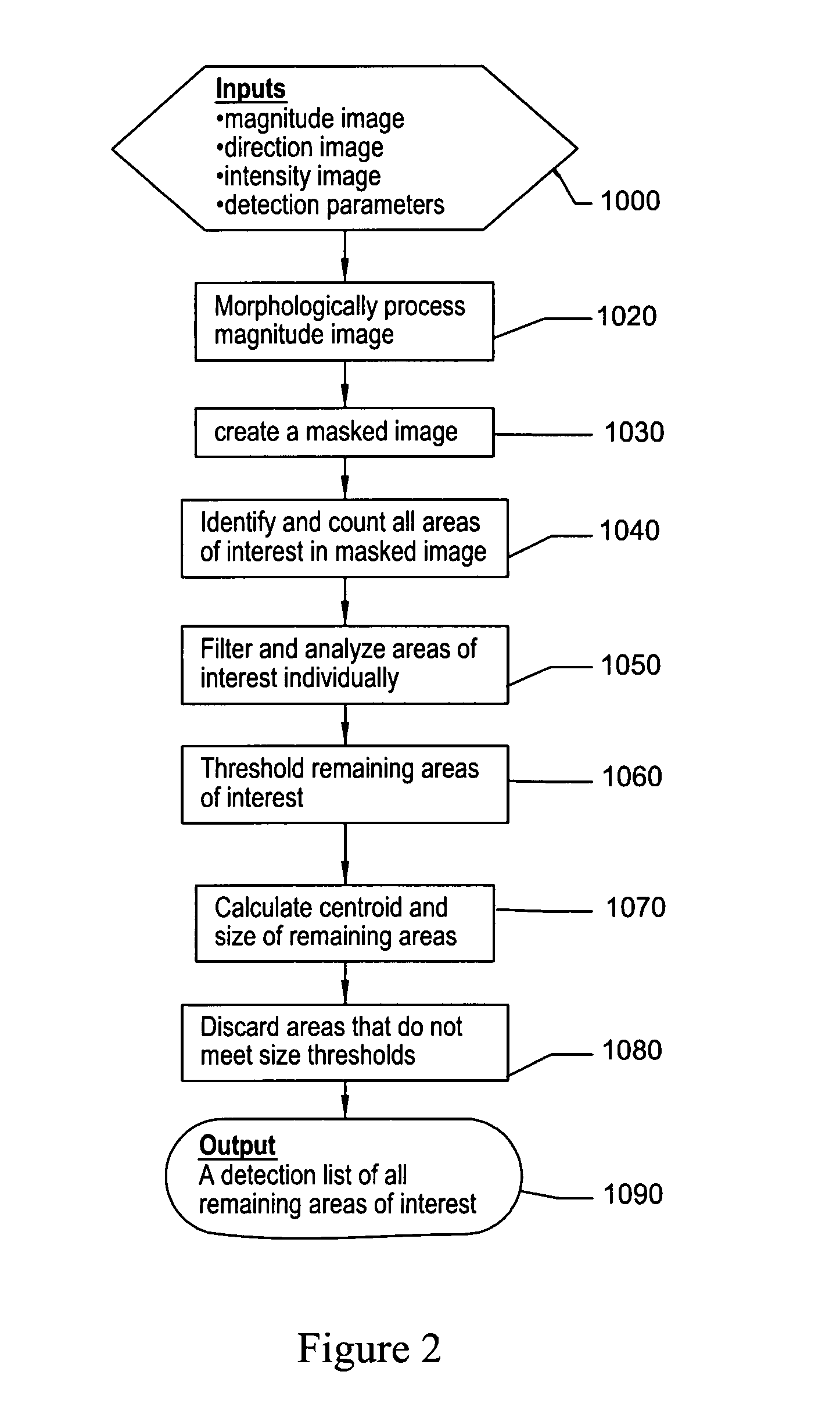
[0037]The inventive method described herein pertains to the automated detection of objects or areas of interest in an image. The image may be a still image or part of an incoming stream of data, and may be generated from any number of imaging systems, including infrared, video, x-ray, magnetic resonance, millimeter-wave or combinations or fusions thereof.

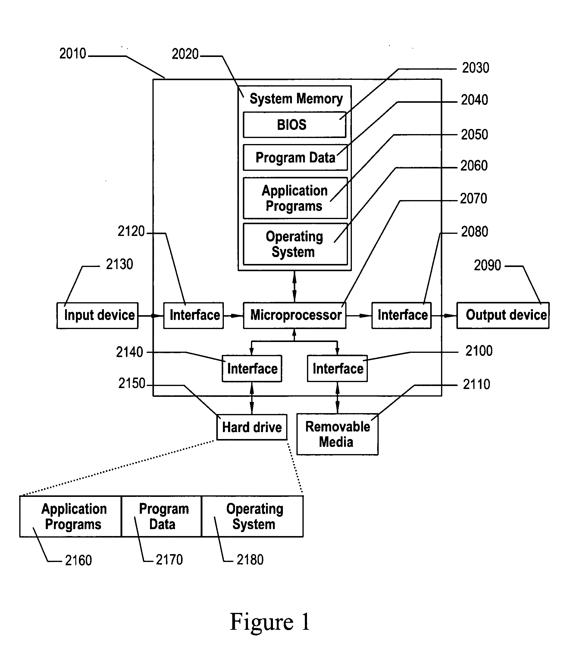
[0038]FIG. 1 shows a diagram of a computer system that is adapted and programmed according to the invention. An embodiment of the inventive method that has been created as a software program may reside in the application programs 2170 area of the hard drive 2150 or in the application program...


PUM


Abstract

Methods for detecting areas of interest in an image using combined edge magnitude and edge direction analysis techniques are presented. One embodiment features using thermal imaging data to detect hotspots in maritime settings that may be potential targets for tracking or weapons systems. The edge magnitude and edge direction data are derived from the intensity image and then combined with the intensity image and analyzed morphologically to remove noise and background elements. The combined image data is then selectively filtered to remove horizontal non-target elements and then analyzed further against target size information to determine which detected and analyzed hotspots are valid targets. Another embodiment features receiving as input an intensity image along with its associated edge magnitude and edge direction images, which have both been created by a means outside the detection method. Yet another embodiment features a detection method that does not selectively filter out horizontal image elements.

Description

TECHNICAL FIELD OF THE INVENTION[0001]The present invention relates in general to the analysis of multi-dimensional images, and more particularly, to a system and method for extracting the shape and size of an object or area of interest from the background.BACKGROUND OF THE INVENTION[0002]Object recognition involves the analysis of a two-dimensional image in order to identify specific objects or areas of interest. Many systems incorporate a three-step process where a pre-screener identifies regions of interest or candidate objects which are then analyzed by an intermediate discriminator that evaluates each area in more detail. The remaining areas are then further analyzed to positively identify them and establish their location in the image.[0003]Two dimensional imaging systems such as video or Forward-looking Infrared (FLIR) systems analyze incoming information on a nearly continuous basis and must identify and locate any areas of interest identified by the camera or sensor. One me...

Claims


Application Information

Patent Timeline
IPC IPC(8): G06K9/00G06K9/48G06V10/25
CPCG06K9/3233G06T7/0083G06T2207/30232G06T2207/20144G06T2207/30212G06T2207/10048G06T7/12G06T7/194G06V10/25G06T7/00G06T7/40
Inventor SEFCIK, JASON A.
Owner LOCKHEED MARTIN CORP
Why Eureka
Try Eureka