Method for producing solid electrolyte structure, method for producing all-solid-state cell, solid electrolyte structure, and all-solid-state cell

a solid electrolyte and electrolyte technology, applied in the direction of electrode manufacturing process, final product manufacture, climate sustainability, etc., can solve the problems of composite electrodes that cannot be easily handled in the process, composite electrodes are often cracked, and the solution leakage, etc., to achieve excellent connection interface

Inactive Publication Date: 2009-09-10
TOKYO METROPOLITAN UNIVERSITY +1
View PDF5 Cites 70 Cited by
  • Summary
  • Abstract
  • Description
  • Claims
  • Application Information

AI Technical Summary

Benefits of technology

[0035]The solid electrolyte structure and the all-solid-state cell of the present invention contain the porous solid electrolyte portion and the dense solid electrolyte portion in the integrated state with the excellent connection interface.
[0036]The above and other objects, features and advantages of the present invention will become more apparent from the following description when taken in conjunction with the accompanying drawings in which a preferred embodiment of the present invention is shown by way of illustrative example.

Problems solved by technology

The cell using such an electrolytic solution can cause problems of solution leakage, ignition, explosion, etc.
However, the secondary lithium ion cell described in Japanese Laid-Open Patent Publication No. 2006-260887 has the following disadvantages since the further electrolyte has to be connected to the composite electrode composed of the porous solid electrolyte and the cell active material.
(c) The composite electrode cannot be easily handled in the process of pressurization or sintering.
(d) The composite electrode is often cracked in the process of pressurization or sintering.
Particularly, when the composite electrode and the electrolyte have small thicknesses for lowered cell resistance, the problems of (c) and (d) are quite often caused in the integration.

Method used


Image

  • Method for producing solid electrolyte structure, method for producing all-solid-state cell, solid electrolyte structure, and all-solid-state cell
  • Method for producing solid electrolyte structure, method for producing all-solid-state cell, solid electrolyte structure, and all-solid-state cell
  • Method for producing solid electrolyte structure, method for producing all-solid-state cell, solid electrolyte structure, and all-solid-state cell

Examples


first example

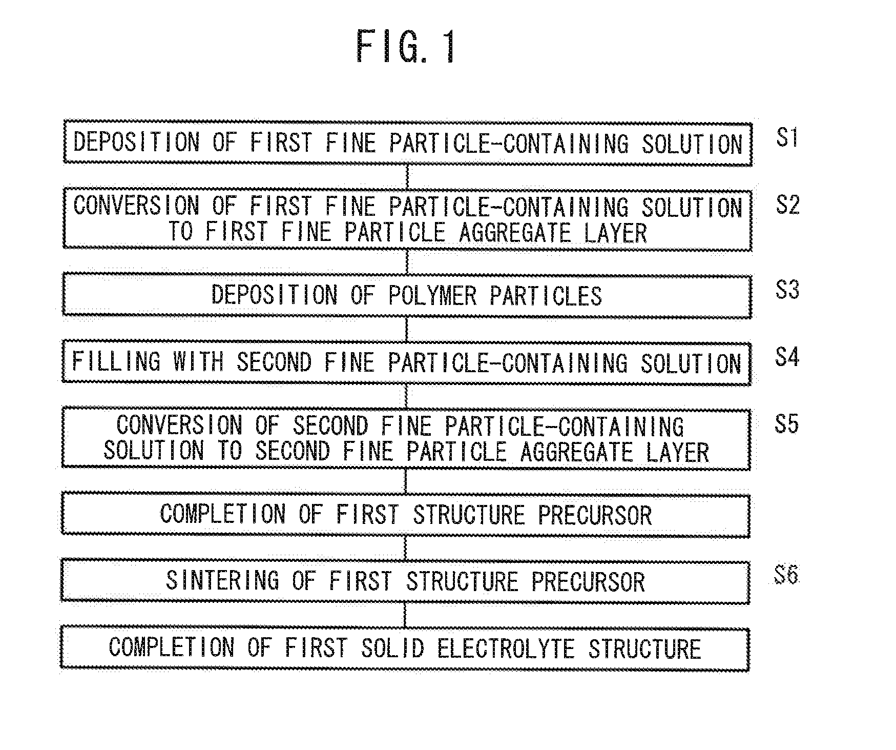
[0157]First Example of a first solid electrolyte structure 24 (see FIG. 3B) produced by the first production method will be described in detail below with reference to FIG. 1.

[0158]In First Example, a filtering unit 70 shown in FIG. 21 is used. In the filtering unit 70, a cylindrical solution supply 74 having a hollow portion 72 is connected to a cylindrical solution discharge nozzle 76. In the connection 78, a solution filter 80 and a packing 82 are fitted to ensure the internal airtightness. The filter 80 has a pore diameter about 1 μm. In the use of the filtration unit 70, a solution containing a mixture of particles is introduced to the solution supply 74 and aspirated through the nozzle 76 under reduced pressure, whereby the solution component is discharged and the particles remain and aggregate on the filter 80.

[0159]In First Example of the first production method, the steps S1 and S2 of FIG. 1 were carried out in one process. A solution containing 9 mg of fine LAGP particles ...

second example

[0162]Second Example of a third solid electrolyte structure 42 (see FIG. 10B) produced by the third production method will be described in detail below with reference to FIG. 7. Also in Second Example, the filtering unit 70 shown in FIG. 21 is used.

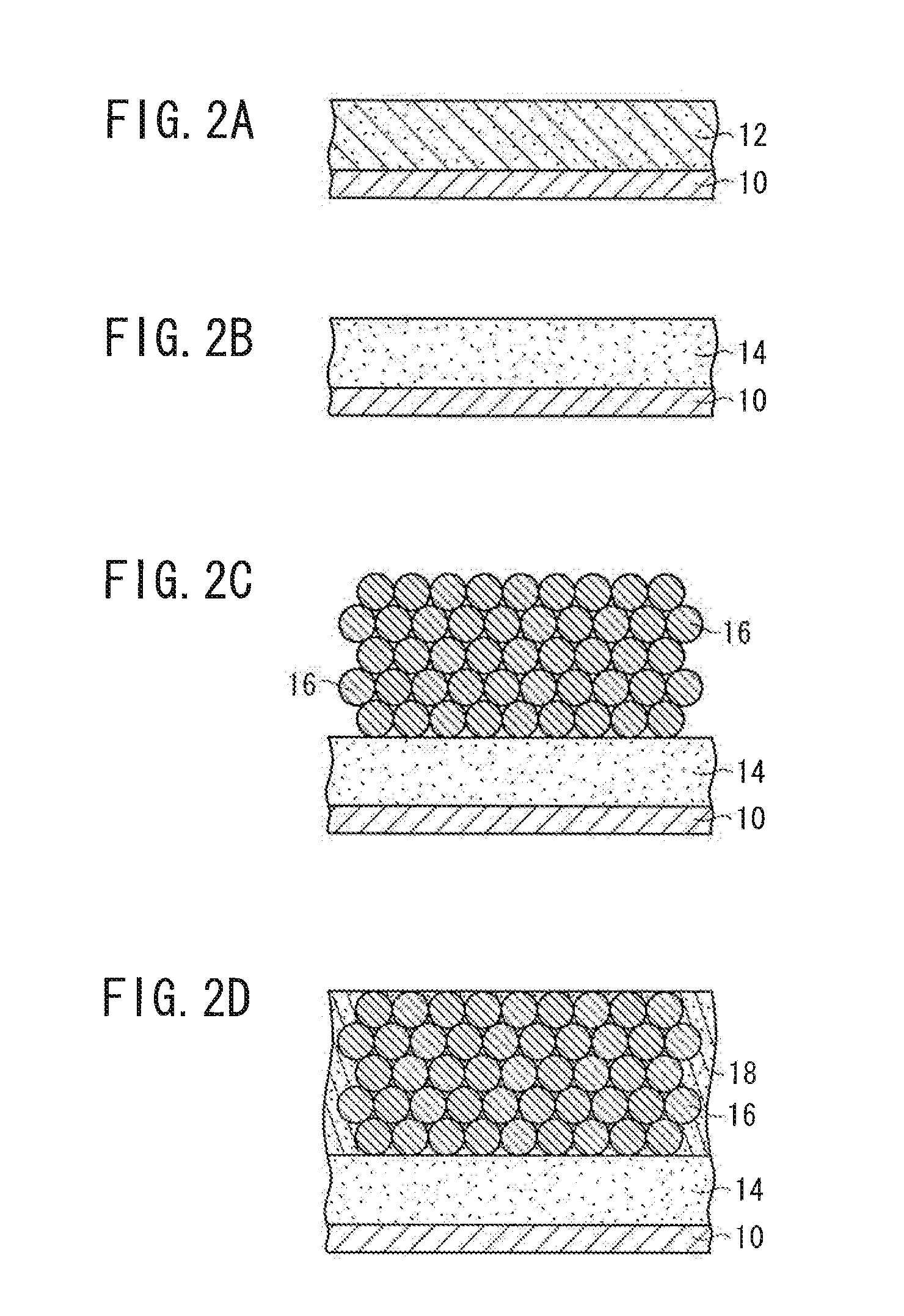
[0163]In Second Example of the third production method, the steps S201 to S203 of FIG. 7 were carried out in one process. A solution containing 30 mg of fine LAGP particles having a particle diameter of approximately 0.5 μm, 0.27 ml of a 10% solution of a polystyrene having a particle diameter of approximately 3 μm, 0.1 ml of a polyethylene glycol having a molecular weight of 400, and 5 ml of H2O was prepared, and mixed under ultrasonic irradiation. The solution was introduced to the filtration unit 70 and slowly suction-filtered at approximately 0.1 kPa. At this stage, a first fine particle aggregate layer 14 containing the fine solid electrolyte particles and the polymer particles 16 was deposited on the filter 80.

[0164]The steps S204 a...

third example

[0168]Third Example of a sixth solid electrolyte structure 60 (see FIG. 18B) produced by the sixth production method will be described in detail below with reference to FIG. 16. Also in Third Example, the filtering unit 70 shown in FIG. 21 is used.

[0169]In Third Example of the sixth production method, the steps S501 to S503 of FIG. 16 were carried out in one process. A solution containing 0.20 ml of a 10% solution of a polystyrene having a particle diameter of approximately 3 μm (available from MAGSPHERE INC.) and 20 ml of H2O was prepared, and mixed under ultrasonic irradiation. The solution was introduced to the filtration unit 70 and slowly suction-filtered at approximately 5 kPa. At this stage, an opal-type polystyrene crystal structure was deposited on the filter 80. The deposited polystyrene structure was separated from the filter 80 and maintained at 110° C. for 1 hour to fuse the polystyrene particles, whereby an opal-type polystyrene crystal structure film (see FIG. 17A) wa...


PUM

PropertyMeasurementUnit
lithium ion conductivityaaaaaaaaaa
particle diameteraaaaaaaaaa

Abstract

A first fine particle-containing solution is deposited on an appropriate substrate, and dried to form a first fine particle aggregate layer. Polymer particles are deposited on the first fine particle aggregate layer, and are supplied with a second fine particle-containing solution such that the polymer particles are immersed in the second fine particle-containing solution. The second fine particle-containing solution is dried to form a second fine particle aggregate layer containing a large number of the polymer particles embedded. A first structure precursor is completed at this stage. Then, the first structure precursor is separated from the substrate, and thermally treated. Thus, the production of a first solid electrolyte structure, which has a porous solid electrolyte portion and a dense solid electrolyte portion integrated, is completed.

Description

CROSS-REFERENCE TO RELATED APPLICATIONS[0001]This application is based upon and claims the benefit of priority from Japanese Patent Application No. 2008-057753 filed on Mar. 7, 2008 and Japanese Patent Application No. 2009-034371 filed on Feb. 17, 2009 in the Japanese Patent Office, of which the contents are incorporated herein by reference.BACKGROUND OF THE INVENTION[0002]1. Field of the Invention[0003]The present invention relates to a method for producing a solid electrolyte structure usable as a base of an all-solid-state cell utilizing a combination of a cell active material and a solid electrolyte (a production method of a solid electrolyte structure), a method for producing an all-solid-state cell using the solid electrolyte structure (a production method of an all-solid-state cell), a solid electrolyte structure, and an all-solid-state cell.[0004]2. Description of the Related Art[0005]In recent years, with the development of portable devices such as personal computers and mo...

Claims


Application Information

Patent Timeline
Patent Type & Authority Applications(United States)
IPC IPC(8): H01M8/10H01M8/00H01M10/0561H01M10/0562H01M10/0585
CPCB32B18/00C04B35/447C04B35/462C04B2235/3203C04B2235/3217C04B2235/3227Y10T29/49108C04B2235/3287C04B2237/34C04B2237/586H01M4/0471H01M10/0562C04B2235/3232Y02E60/10Y02P70/50
Inventor KANAMURA, KIYOSHIHARA, MASANORIOKUDA, SAYAKAYAMAMOTO, KAZUHIROSATO, YOSUKE
Owner TOKYO METROPOLITAN UNIVERSITY
Why Eureka
Try Eureka