Detonative cleaning apparatus mounting system

a technology of mounting system and cleaning apparatus, which is applied in the direction of cleaning equipment, cleaning hollow objects, light and heating apparatus, etc., can solve the problems of reducing efficiency and throughput, difficult direct access to fouled surfaces, and large industrial equipment surface fouling

Inactive Publication Date: 2009-09-17
SHOCKSYST
View PDF3 Cites 21 Cited by
  • Summary
  • Abstract
  • Description
  • Claims
  • Application Information

AI Technical Summary

Benefits of technology

[0005]Accordingly, one aspect of the disclosure involves an apparatus for cleaning a surface within a vessel. An elongate combustion conduit extends from an upstream end to a downstream end associated with an aperture in the wall of the vessel and positioned to direct a shockwave toward the surface. One or more hangers support the combustion conduit at one or more locations along a length of the combustion conduit. A penetration conduit is positioned between the wall aperture and an associated portion of the combustion conduit. Means couple the combustion conduit to the penetration conduit so as to accommodate one or both of relative longitudinal movement and relative angular movement.

Problems solved by technology

Surface fouling is a major problem in industrial equipment.
Such particulate build-up may progressively interfere with plant operation, reducing efficiency and throughput and potentially causing damage.
Often direct access to the fouled surfaces is difficult.

Method used


Image

  • Detonative cleaning apparatus mounting system
  • Detonative cleaning apparatus mounting system
  • Detonative cleaning apparatus mounting system

Examples


Embodiment Construction

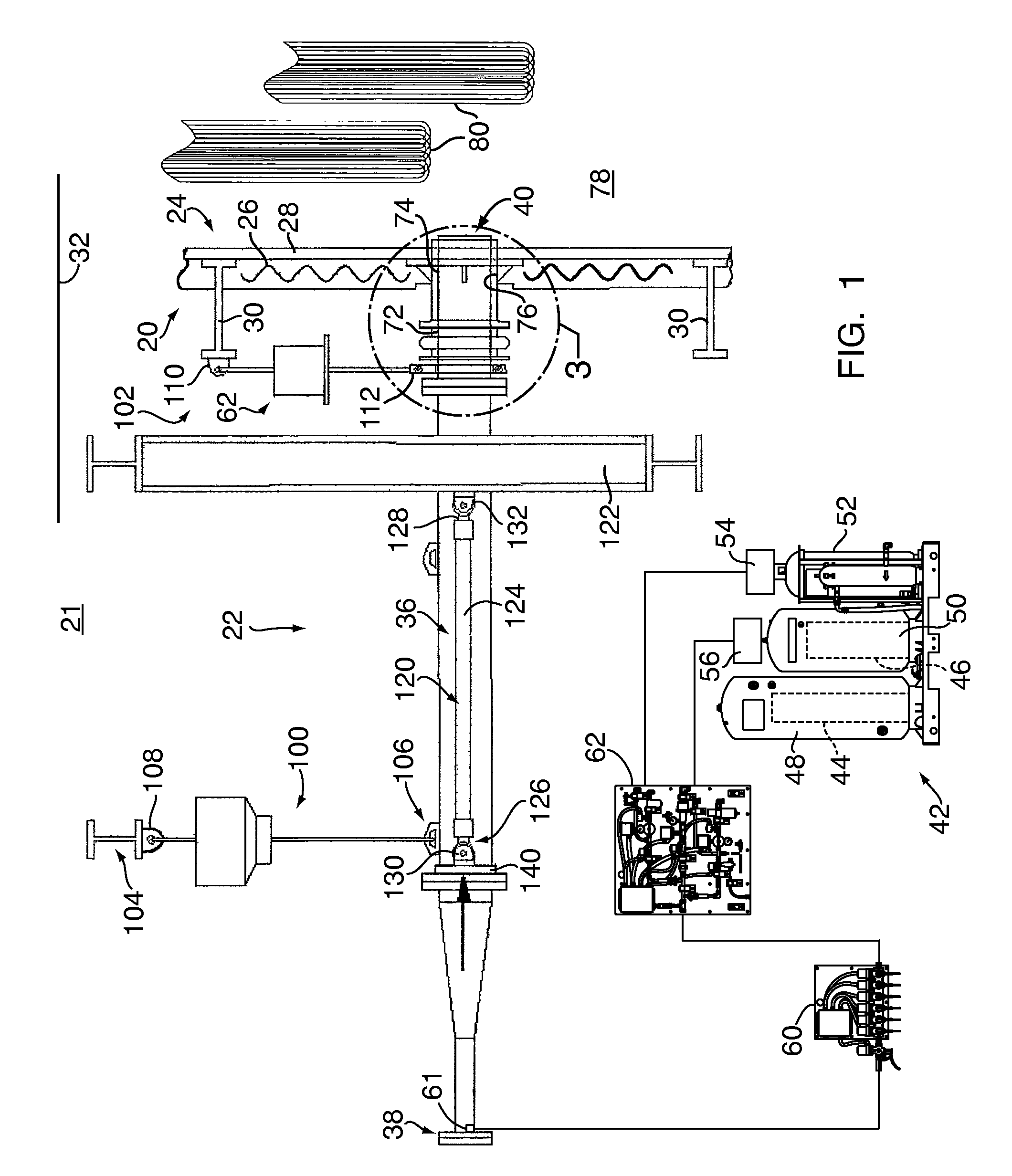
[0033]FIG. 1 shows a vessel (e.g., a boiler) 20 in a building 21. One or more soot blower apparatus (soot blowers) 22 are positioned to clean surfaces within the vessel interior 78. The exemplary vessel comprises a wall 24. The exemplary wall 24 may include a structural and / or insulative outer layer 26 and an inner layer 28. In high temperature locations along the wall 24, the inner layer 28 may be a heat transfer layer formed of fluid (e.g., water)-carrying tubes. Exemplary tubes are welded together to form a membrane wall. In lower temperature locations, the inner layer 28 may be a steel plate. For further structural reinforcement against internal or external pressure loads, the wall 24 may include reinforcements commonly known as buckstays 30. Exemplary buckstays 30 are steel I-beams secured to each other and to the remaining wall structure to form a rigid enclosure. The wall 24 is subject to thermal growth as the vessel temperature increases. The growth may be accommodated by su...


PUM


Abstract

An apparatus for cleaning a surface within a vessel has an elongate combustion conduit extending from an upstream end to a downstream end. The downstream end is associated with an aperture in the wall of the vessel and is positioned to direct a shockwave toward the surface. At least one hanger supports the combustion conduit at least one location along a length of the combustion conduit. A penetration conduit is positioned between the wall aperture and an associated portion of the combustion conduit. Means couple the combustion conduit to the penetration conduit so as to accommodate relative longitudinal movement and/or relative angular movement.

Description

CROSS-REFERENCE TO RELATED APPLICATIONS[0001]This application claims priority from and incorporates in its entirety by reference U.S. Provisional Patent Application Ser. No. 61 / 028,491, filed Feb. 13, 2008, entitled “Detonative Cleaning Apparatus Mounting.”TECHNICAL FIELD OF THE INVENTION[0002]The disclosure relates to industrial equipment. More particularly, the disclosure relates to the detonative cleaning of industrial equipment.BACKGROUND OF THE INVENTION[0003]Surface fouling is a major problem in industrial equipment. Such equipment includes furnaces (coal, oil, waste, etc.), boilers, gasifiers, reactors, heat exchangers, and the like. Typically, the equipment involves a vessel containing internal heat transfer surfaces that are subjected to fouling by accumulating particulate such as soot, ash, minerals and other products and byproducts of combustion, more integrated buildup such as slag and / or fouling, and the like. Such particulate build-up may progressively interfere with p...

Claims


Application Information

Patent Timeline
Patent Type & Authority Applications(United States)
IPC IPC(8): F23J3/02
CPCB08B7/0007B08B7/02F28G7/005F28G7/00B08B9/08
Inventor HENDERSON, RAYMOND N.LUPKES, KIRK R.
Owner SHOCKSYST
Why Eureka
Try Eureka