Method for controlling a flowrate of a recirculated exhaust gas

a flow rate and exhaust gas technology, applied in the direction of hot gas positive displacement engine plants, combustion engines, engine controllers, etc., can solve the problems of accelerate corrosion and fouling of internal components

Active Publication Date: 2009-09-17
GENERAL ELECTRIC CO
View PDF4 Cites 90 Cited by
  • Summary
  • Abstract
  • Description
  • Claims
  • Application Information

AI Technical Summary

Benefits of technology

[0007]For the foregoing reasons, there is a need for a method for controlling the composition of the inlet fluid exiting

Problems solved by technology

Left untreated, these constituents will accelerate corrosion and fou

Method used


Image

  • Method for controlling a flowrate of a recirculated exhaust gas
  • Method for controlling a flowrate of a recirculated exhaust gas
  • Method for controlling a flowrate of a recirculated exhaust gas

Examples


Embodiment Construction

[0014]The following detailed description of preferred embodiments refers to the accompanying drawings, which illustrate specific embodiments of the invention. Other embodiments having different structures and operations do not depart from the scope of the present invention.

[0015]Certain terminology is used herein for the convenience of the reader only and is not to be taken as a limitation on the scope of the invention. For example, words such as “upper,”“lower,”“left,”“right,”“front”, “rear”, “top”, “bottom”, “horizontal,”“vertical,”“upstream,”“downstream,”“fore”, “aft”, and the like: merely describe the configuration shown in the Figures. Indeed, the element or elements of an embodiment of the present invention may be oriented in any direction and the terminology, therefore, should be understood as encompassing such variations unless specified otherwise.

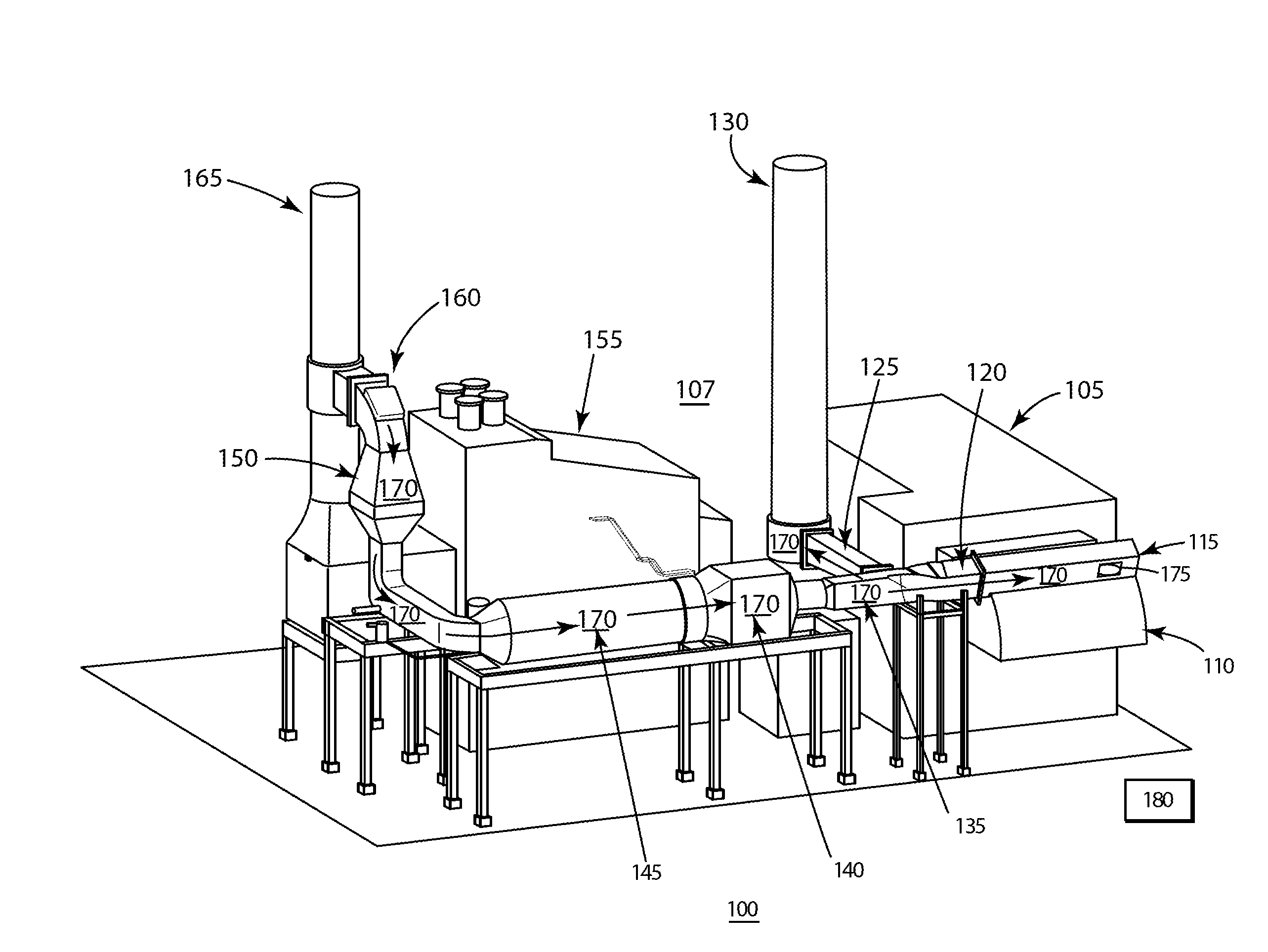
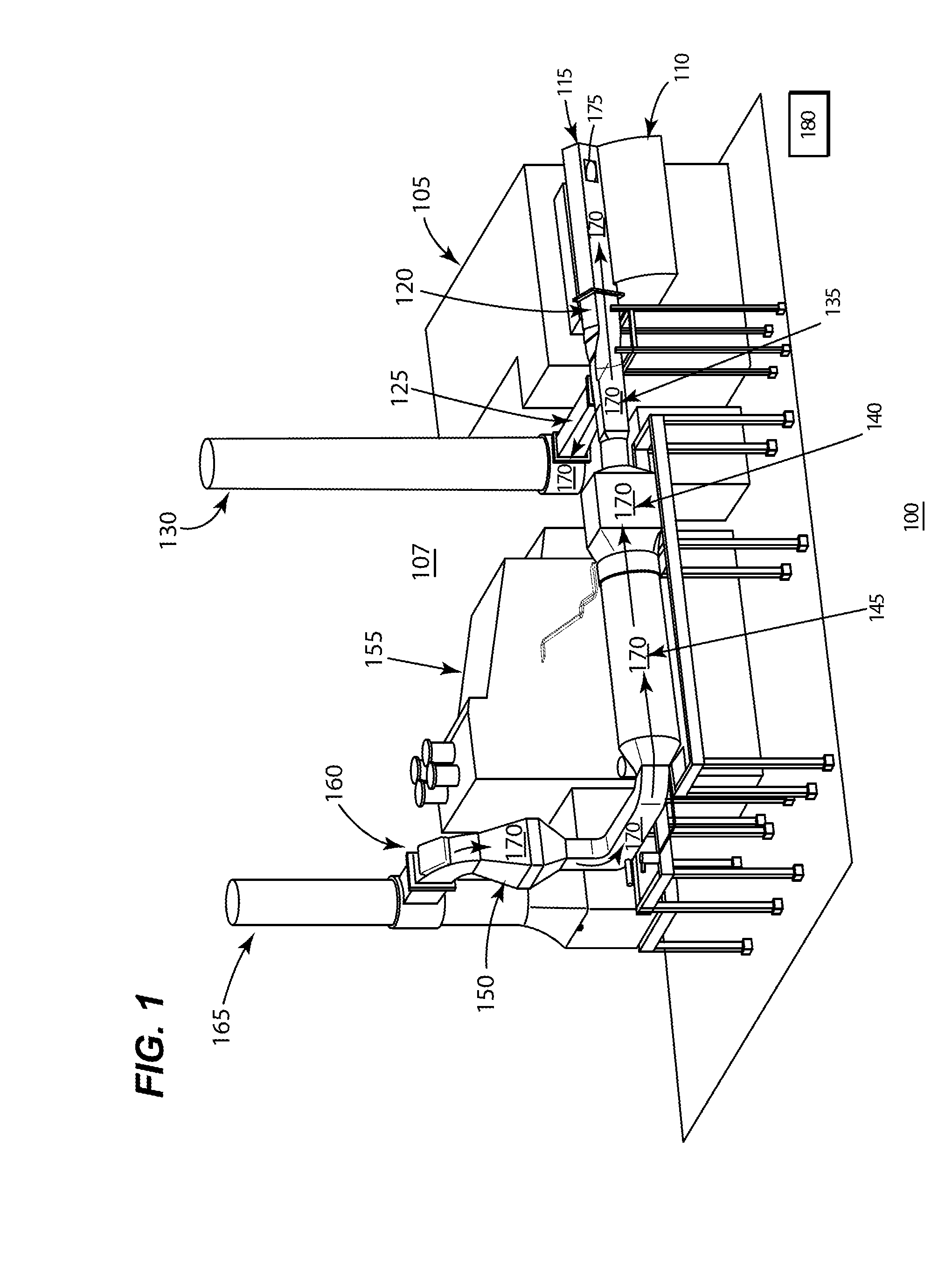
[0016]An EGR rate may be considered the rate at which a recirculated exhaust stream enters the turbomachine. In the present inven...


PUM


Abstract

A method for controlling a turbomachine exhaust gas recirculation (EGR) system is provided. The EGR system may allow for the removal and sequestration of at least one constituent within the exhaust before the recirculation occurs.

Description

[0001]This application is related to commonly-assigned U.S. patent application Ser. No. 11 / 928,038 [GE Docket 227348], filed Oct. 30, 2007; U.S. patent application Ser. No. 11 / 953,524 [GE Docket 228179], filed Dec. 10, 2007; U.S. patent application Ser. No. 11 / 953,556 [GE Docket 229334], filed Dec. 10, 2007; and U.S. patent application Ser. No. 11 / 956,679 [GE Docket 229945], filed Dec. 14, 2007.BACKGROUND OF THE INVENTION[0002]The present invention relates to an exhaust gas recirculation system, and more particularly to a method and system for controlling the quantity of exhaust reentering a turbomachine after processing by a recirculation system.[0003]The emissions from a turbomachine, such as a gas turbine, are closely regulated. There is a growing concern over the long-term effects of Nitrogen Oxides (hereinafter NOx), Carbon Dioxide (hereinafter “CO2”) and Sulfur Oxides (SOx) emissions on the environment. Operators of turbomachines desire methods of reducing the levels of NOx, C...

Claims


Application Information

Patent Timeline
IPC IPC(8): F02B33/44
CPCF02C9/16F02C3/34
Inventor OUELLET, NOEMIE DIONFULLER, JASON D.HIBSHMAN, II, JOELL R.
Owner GENERAL ELECTRIC CO
Why Eureka
Try Eureka