Heat-exchanger sealing

Inactive Publication Date: 2009-09-17
ZANAQUA TECH
View PDF11 Cites 34 Cited by
  • Summary
  • Abstract
  • Description
  • Claims
  • Application Information

AI Technical Summary

Benefits of technology

[0011]But I have found a way to reduce this cost significantly. To seal the divider to opposed counterflow-heat-exchanger cover members, I use a gasket so shaped as both to plug the divider's end openings and to form a sealing ridge with which complementary, substantially parallel sealing surfaces on the cover members can mate. Preferably, the gasket is provided by over-molding. That is, the divider is placed in a mold, and material that cures into rubber or some other deformable material is injected into the mold to mold the gasket onto the divider. In short, simple injection molding replaces laborious soldering or welding.
[0012]Additionally, I have found a way to facilitate over-molding such a gasket. To prevent the molten gasket material from flowing farther than desired down the channels that the divider's folds create, those channels need to be plugged by teeth of some sort that extend into those channels, and the mold's interior surface may be shaped to form such teeth. But it turns out that the gasket material tends to stick to the teeth, so extracting the resultant divider-and-gasket assembly from such a mold can present difficulties that add great

Problems solved by technology

But it turns out that the gasket material tends to stick to the teeth, so extracting the resultant divi

Method used


Image

  • Heat-exchanger sealing
  • Heat-exchanger sealing
  • Heat-exchanger sealing

Examples


Embodiment Construction

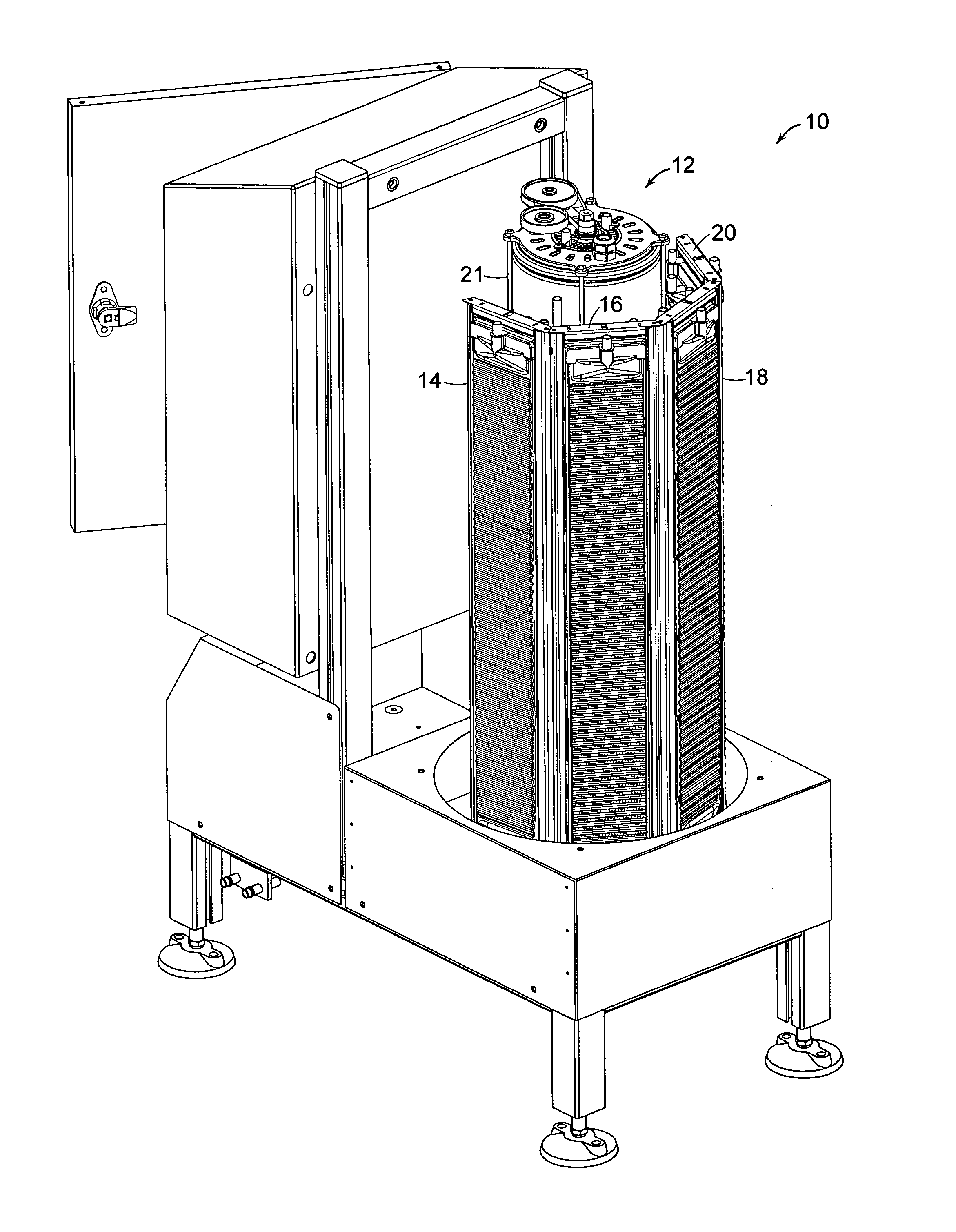
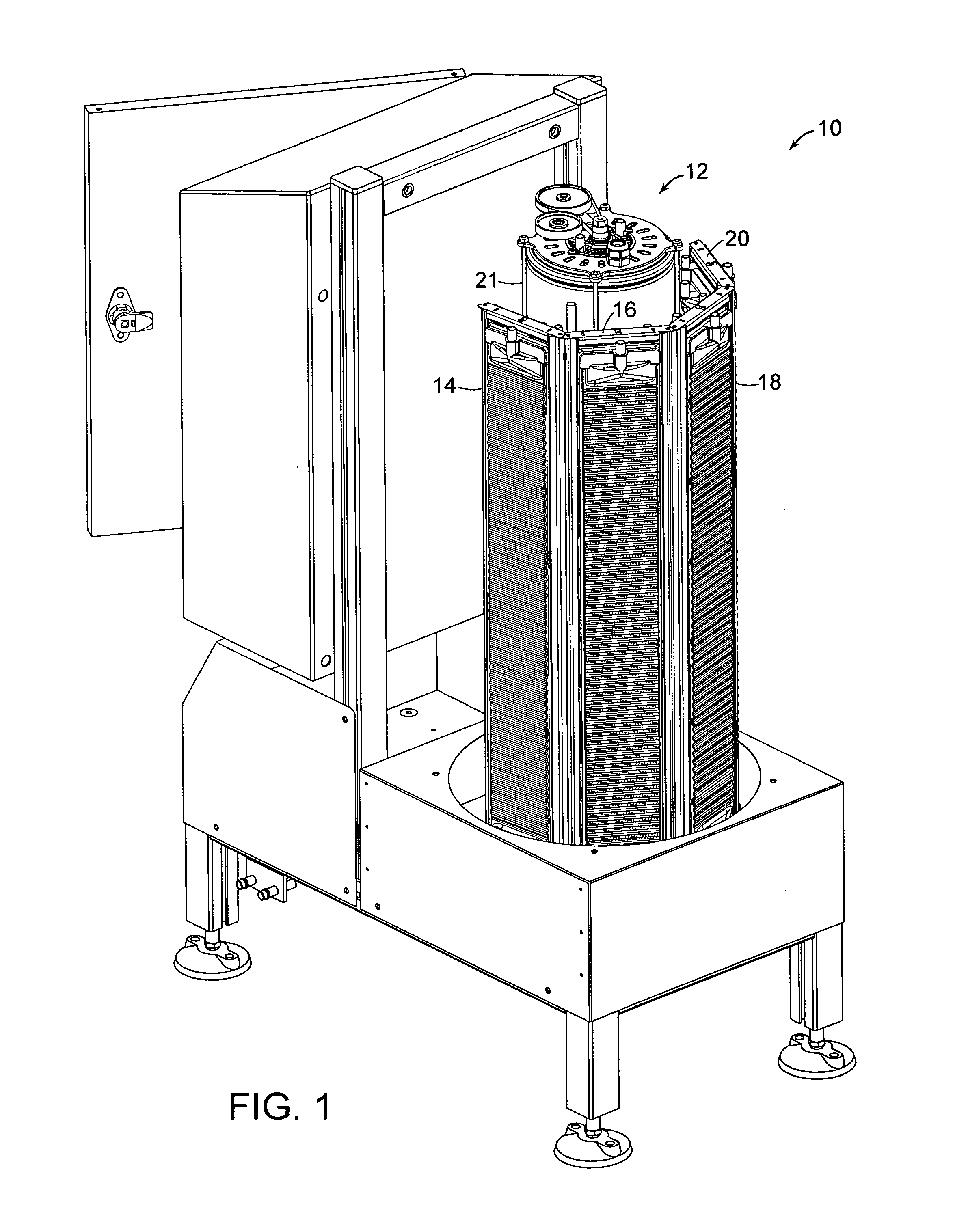
[0031]FIG. 1 depicts a distiller 10 in which rotary heat exchanger 12 produces purified distillate from contaminated influent and rejects the contaminates in a concentrate. A counterflow heat exchanger comprising four identical modules 14, 16, 18, and 20 operating in series receives the distillate and concentrate from the rotary heat exchanger 12 and transfers heat from them to the influent, which the counterflow heat exchanger then supplies to the rotary heat exchanger.

[0032]Specifically, influent that the distiller receives at an influent port not shown is pumped in one direction through the counterflow-heat-exchanger modules 14, 16, 18, and 20, where the influent absorbs heat from distillate and concentrate that flow through those modules in the opposite direction. Because of the opposite-direction flow, the influent is placed in thermal communication with increasingly hot distillate and concentrate as it advances through the counterflow heat exchanger and itself becomes hotter: ...


PUM

PropertyMeasurementUnit
Fractionaaaaaaaaaa
Poweraaaaaaaaaa
Poweraaaaaaaaaa

Abstract

A distiller's counterflow-heat-exchanger module includes thermally conductive distillate and concentrate dividers across which heat flows to an influent liquid from distillate and concentrate liquids, respectively. The distillate divider's shape is convoluted in such a manner as to form alternating distillate and influent channels having end openings. A peripheral gasket is so over-molded onto the distillate divider that it forms plugs that seal the end openings from each other and further forms a ridge providing surfaces against which opposed generally planar parallel surfaces of cover members can be urged to form a peripheral seal.

Description

BACKGROUND OF THE INVENTION[0001]1. Field of the Invention[0002]The present invention concerns counterflow heat exchangers and finds particular application in those that are components of mass-produced distillers.[0003]2. Background Information[0004]Distillation is probably the single most effective approach to purifying water. But it has historically been too costly for widespread use. Distillation requires that the water evaporate. Without energy recovery, the energy of vaporization alone would cost something on the order of fifteen to twenty cents per gallon or more. Theoretically, that cost can be reduced by recovering and reusing the heat of vaporization. For most small-scale distillation applications, though, the equipment available until now has not had the capability of recovering enough heat to make distillation affordable.[0005]But more-recent designs have shown that small, low-component-cost distillers can distill water with high efficiency. For example, a fire-plug-sized...

Claims


Application Information

Patent Timeline
IPC IPC(8): F28F3/10
CPCF28F2230/00B01D1/22B01D5/006F28F2255/14F28D9/0043F28D9/0093F28D9/0025
Inventor ZEBUHR, WILLIAM H.
Owner ZANAQUA TECH
Why Eureka
Try Eureka