Electrostatic chuck
a technology of electrostatic chucks and chucks, which is applied in the direction of chucks, mechanical equipment, manufacturing tools, etc., can solve the problems of electrostatic chuck breakage, wafer damage, and particle deposited,
- Summary
- Abstract
- Description
- Claims
- Application Information
AI Technical Summary
Problems solved by technology
Method used
Image

Examples
modification 1
(Modification 1)
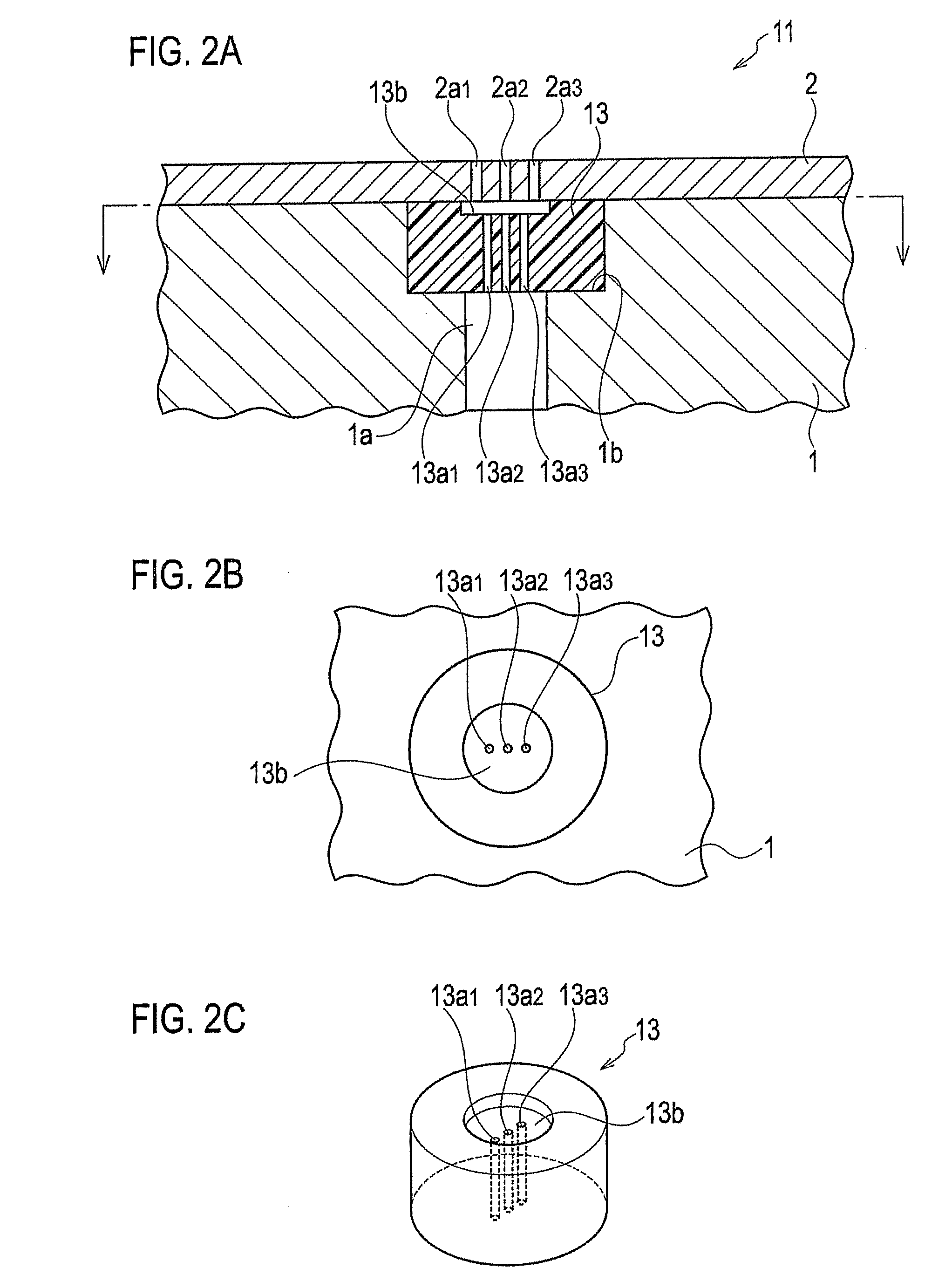
[0054]In an arc prevention member 13 illustrated in FIGS. 2A to 2C, a sub-counter bore portion 13b having a diameter smaller than the outer diameter of the arc prevention member 13 is provided to the electrostatic chuck body 2-side main plane. An insulating member having a plurality of through-holes 13a1, 13a2, and 13a3 is provided from the bottom surface of the sub-counter bore portion 13b to the cooling device 1-side main plane and has a diameter smaller than the inner diameter of the gas supply port 1a. It is preferable that the plurality of through-holes and the pores of the electrostatic chuck body 2 be arranged so as not to overlapped with each other as seen from a vertically upward direction of the electrostatic chuck. Three through-holes are shown in the drawing, but there may be more.
[0055]According to Modification 1, it is difficult to generate plasma in the gas supply port 1a due to the reduced space through which the back side gas flows. Although the reas...
modification 2
(Modification 2)
[0056]In an arc prevention member 23 illustrated in FIGS. 3A to 3C, a sub-counter bore portion 23b having a diameter smaller than the outer diameter of the arc prevention member 23 is provided to the electrostatic chuck body 2-side main plane. A plurality of grooves 23a1 and 23a2 are provided in the surface of the arc prevention member and defined around a centerline in a cross-sectional view in a gas flow direction of the arc prevention member 23 so as to provide gas paths when the arc prevention member 23 is inserted into the main counter bore portion 1b. In an arc prevention member 33 illustrated in FIGS. 4A to 4C, grooves 33a1, 33a2, 33a3, and 33a4 are provided, as illustrated in FIGS. 4B and 4C, by increasing the number of grooves 23a1 and 23a2 of FIGS. 3B and 3C.
[0057]According to Modification 2, arcing can be prevented for the same reason as that of Modification 1.
modification 3
(Modification 3)
[0058]FIGS. 5A to 5C show an arc prevention member 43. As shown in FIG. 5C, the arc prevention member 43 is provided with a cross-shaped sub-counter bore portion 43b formed of two grooves 43b1 and 43b2 intersecting at a central portion in a radial direction of the arc prevention member 43 on a main plane of the arc prevention member 43 on the electrostatic chuck body 2 side. As shown in FIG. 5A, this has a plurality of planar cutouts 43c1, 43c2, 43c3 and 43c4, which run straight in a longitudinal direction of grooves 43b1 and 43b2 of the cross-shaped sub-counter bore portion 43b, on the cylindrical side surface 43a (43a1, 43a2, 43a3 and 43a4) as shown in FIG. 5B so as to form a gas path 1c when the arc prevention member 43 is inserted into the main counter bore portion 1b. It is preferable that the diameter of the arc prevention member 43 is smaller than that of the main counter bore portion 1b as shown in FIG. 5B. This is because, since the back side gas flows throu...
PUM
| Property | Measurement | Unit |
|---|---|---|
| Fraction | aaaaa | aaaaa |
| Pressure | aaaaa | aaaaa |
| Pressure | aaaaa | aaaaa |
Abstract
Description
Claims
Application Information
 - Generate Ideas
- Intellectual Property
- Life Sciences
- Materials
- Tech Scout
- Unparalleled Data Quality
- Higher Quality Content
- 60% Fewer Hallucinations
Browse by: Latest US Patents, China's latest patents, Technical Efficacy Thesaurus, Application Domain, Technology Topic, Popular Technical Reports.
© 2025 PatSnap. All rights reserved.Legal|Privacy policy|Modern Slavery Act Transparency Statement|Sitemap|About US| Contact US: help@patsnap.com