Wheel suspension for steered wheels of motor vehicles

a technology for steered wheels and motor vehicles, applied in the directions of loading/unloading vehicle arrangment, transportation and packaging, transportation items, etc., can solve problems such as vertical adjustment, and achieve the effects of low wear, easy installation, and effective vibration damping

Active Publication Date: 2009-09-17
AUDI AG
View PDF4 Cites 14 Cited by
  • Summary
  • Abstract
  • Description
  • Claims
  • Application Information

AI Technical Summary

Benefits of technology

[0013]To achieve effective vibration damping, the adjusting nut with the spring plate molded on can furthermore act on the helical compression spring by way of the rubber-elastic damping ring and the axial anti-friction bearing.
[0014]If the shock absorber bearing is located between the bearing plate and the base plate of the base part which can be joined to the body, the entire McPherson strut unit with the attached actuator can be produced as a preassembly unit and can be easily installed in the motor vehicle in a manner favorable to installation.
[0015]Conventionally, the inertia drive can be a ball screw mechanism with balls guided between the spindle and the adjusting nut in ball races, which is characterized by especially easy actuation and low-wear, durable accommodation of actuating forces.
[0016]Finally, the adjusting nut can be advantageously movably guided positively on a section of the guide sleeve which projects down in the peripheral direction by way of a guide ring which projects radially to the inside so that the adjusting nut is guided to be axially movable, but non-rotatable in a manner which is simple in terms of production engineering.

Problems solved by technology

The problem is when, as in the aforementioned McPherson front axle, the shock absorber and the helical compression spring turn at the same time in a wheel deflection.
This results in that for the steering motion of the wheels the adjusting nuts would turn relative to the remaining actuator and would unintentionally cause vertical adjustment.

Method used


Image

  • Wheel suspension for steered wheels of motor vehicles
  • Wheel suspension for steered wheels of motor vehicles
  • Wheel suspension for steered wheels of motor vehicles

Examples


Embodiment Construction

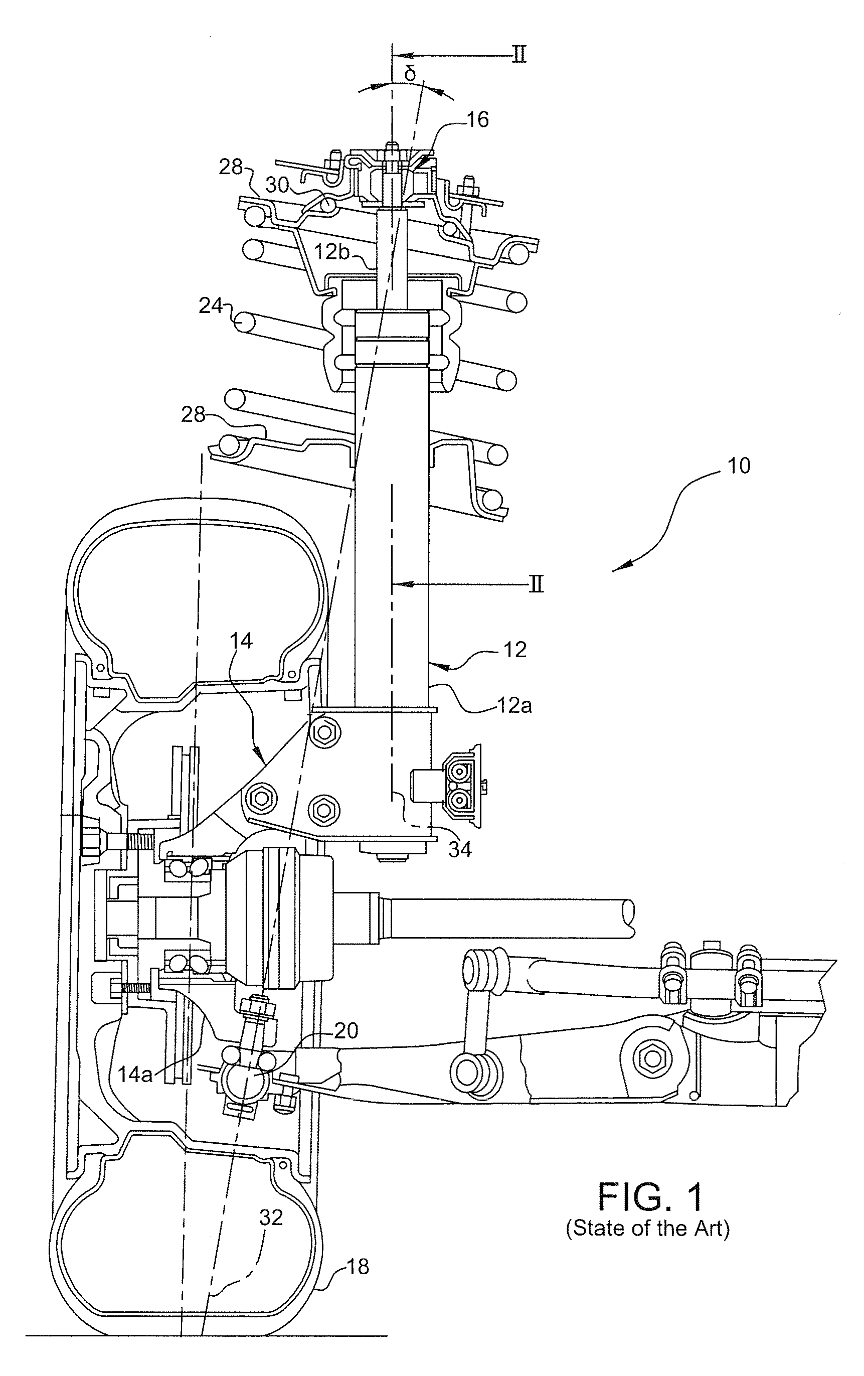
[0019]The McPherson wheel suspension 10 which is shown in FIG. 1 and which corresponds to the prior art is only described to the extent necessary for understanding of this invention.

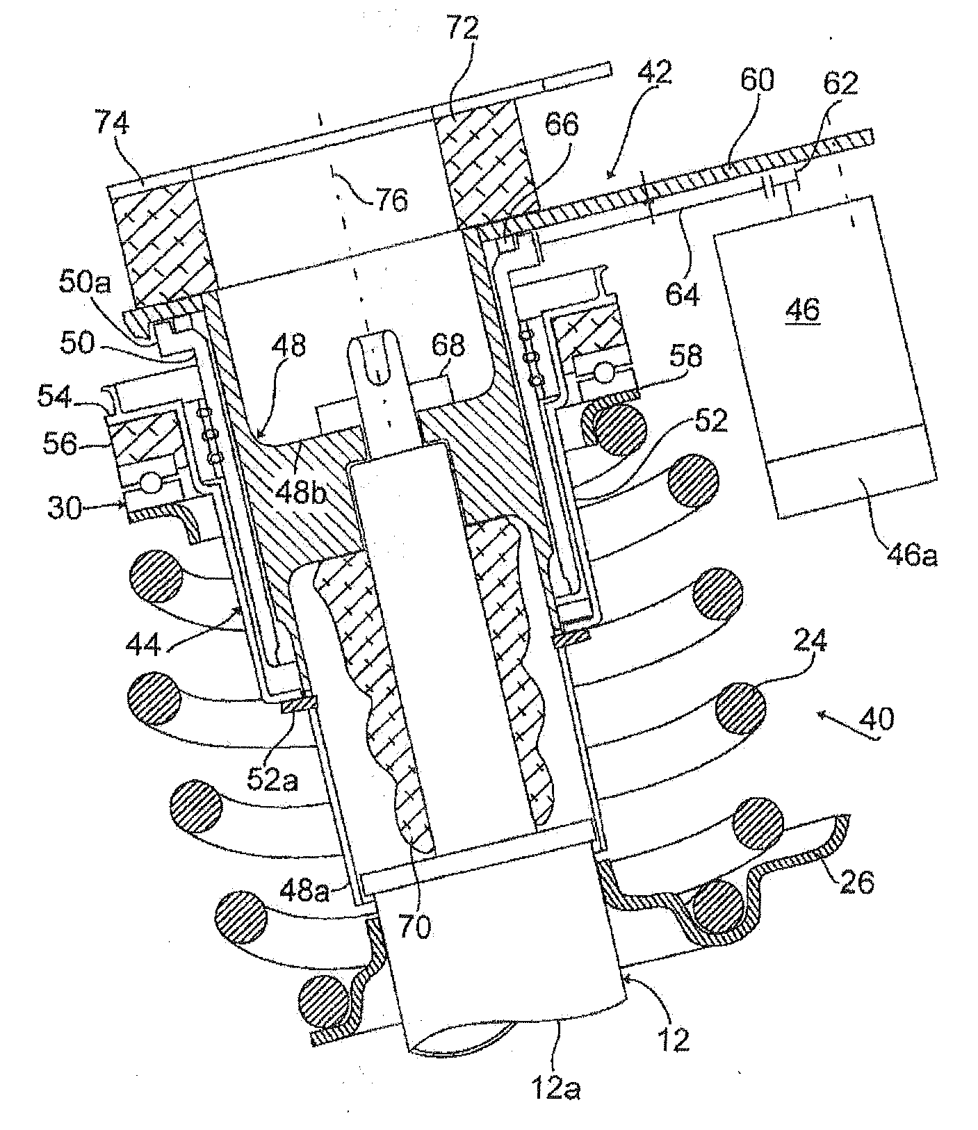
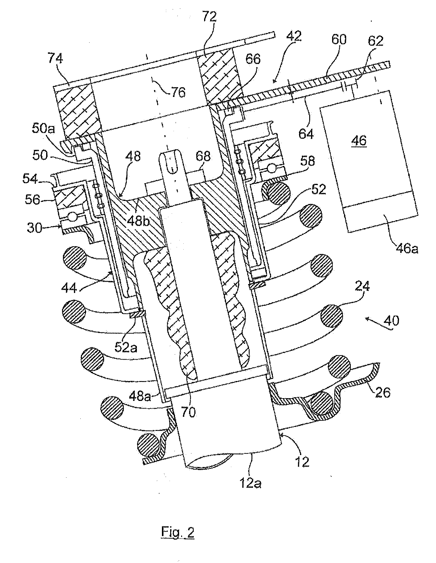
[0020]The wheel suspension 10 has a telescoping shock absorber 12 whose shock absorber tube 12a is permanently connected to the wheel carrier 14. The fixed connection of the telescoping shock absorber 12 to the wheel carrier 14 should be understood as a rigid connection between the two components without bearings. The piston rod 12b of the shock absorber 12 which projects up is coupled to the body (not shown) of the motor vehicle by way of a rubber-elastic shock absorber bearing 16.

[0021]The wheel 18 of the motor vehicle is pivoted on the wheel carrier 14. Furthermore, the wheel carrier 14 with a lower arm 14a is joined by way of a ball-and-socket joint 20 to the lower suspension arm 22 of the wheel suspension 10. The steering means of the motor vehicle (e.g., rack and pinion steering) coupled to the ste...


PUM


Abstract

The invention relates to a wheel suspension for steered wheels of motor vehicles having a telescoping shock absorber which is preferably permanently connected to the wheel carrier and a helical compression spring which surrounds it and which is clamped between a lower spring plate which is preferably permanently connected to the shock absorber tube and an upper, body-side spring plate. According to the invention for vertical adjustment of the body around the shock absorber there is an actuator, and the actuator acts by way of an actuating pinion with the interposition of an axial anti-friction bearing on the upper spring plate.

Description

BACKGROUND OF THE INVENTION [0001]The invention relates to a wheel suspension for steered wheels of motor vehicles.[0002]Such wheel suspensions for steered wheels of motor vehicles are often known as McPherson front axles, with the property of a wheel-guiding telescoping shock absorber whose shock absorber tube is permanently connected to the wheel carrier and whose piston rod is coupled on the body side. The steering axle of the wheel suspension is defined here by the upper coupling point of the piston rod and the lower coupling point of the wheel carrier on a suspension arm.[0003]The shock absorber in a McPherson front axle is wheel-guiding, i.e., the wheel contact force applies a moment to the piston rod and thus to the entire shock absorber system. The transverse forces resulting from the wheel contact forces on the shock absorber guides are equalized by the axial offset of the spring axis and shock absorber axis, i.e., an asymmetrical incline of the helical compression spring t...

Claims


Application Information

Patent Timeline
Patent Type & Authority Applications(United States)
IPC IPC(8): B60G17/015B60G17/00
CPCB60G15/063B60G15/068B60G15/07B60G17/0157B60G17/021B60G2200/44B60G2500/30B60G2202/42B60G2204/1242B60G2204/128B60G2204/41B60G2204/418B60G2202/312
Inventor MICHEL, WILFRIED
Owner AUDI AG
Why Eureka
Try Eureka