
Control apparatus

a control apparatus and control technology, applied in transmission, power network operation system integration, sustainable buildings, etc., can solve problems such as abnormal operation status of electrical load, electrical load faulty, and electrical load disconnected from output, and achieve the effect of convenient remote control and convenient control

Inactive Publication Date: 2009-09-17
RYAN LIAM ANTHONY +2
View PDF8 Cites 14 Cited by
  • Summary
  • Abstract
  • Description
  • Claims
  • Application Information

AI Technical Summary

Benefits of technology

[0075]A further advantage of the invention is achieved when the control means is adapted for comparing the second output signal outputted by the second monitoring means, which is indicative of the level of the current being drawn through the output means with an upper or lower current threshold limit, since if the current being drawn through the output means exceeds the upper current threshold limit, a status message can be immediately transmitted from the control apparatus to the remote communications device which is indicative of the current being drawn by the electrical load. The status of the load can be determined from the current being drawn, and if the load is determined as being faulty, the faulty load which is drawing excessive current may be switched off by a control signal from the remote communications device, or alternatively, by the control means where the control means is programmed to be responsive to excess current being drawn through the output means for operating the switch circuit for isolating the output means from the input means. Alternatively, if the excessive current is determined as being caused by a number of loads being coupled to the output means, or indeed by one load, and the current being drawn would indicate that at a particular time period during the day or night, such a current would lead to the power consumption in a house or the like being excessive, the switch circuit may be operated under the control of the control means for isolating the output means from the input means for the relevant particular time period. Similarly, where the current being drawn is below the lower current threshold limit, the switch circuit may be operated by the control means or by a control signal from the remote communications device for isolating the load from the electrical power supply. Alternatively, the reason the electrical load is drawing a current below the lower current threshold limit can be investigated.
[0076]A further advantage of the invention is achieved when the control means is responsive to a status request from the remote communications device, in that the status of the load and other aspects of the control apparatus can be communicated via appropriate status messages from the control apparatus.
[0077]The provision of more than one output means, which preferably, are independent of each other and each are provided with a corresponding switch circuit, has the added advantage that a number of electrical loads can be controlled independently of each other. A further advantage of providing more than one output means is that if two similar type loads, for example, two lights in a room for security purposes, are coupled separately to two of the output means, on the control means determining from the second output signal from the second monitoring means of one of the output means that the corresponding light has failed, the control means can readily operate the switch circuit of that output means for isolating that output means from the input means, and operate the switch circuit of the other output means which is also coupled to a light for coupling the output means of that light to the input means, thereby maintaining a light on in the room.
[0078]A particularly important advantage of the invention is achieved when the control apparatus is supplied as a single integral unit, and in particular, as a single integral unit with the input means provided by an electrical plug which is suitable for engaging in an electrical socket, and each output means provided as an electrical socket which is suitable for receiving an electrical plug from a load to be electrically coupled thereto. This advantage is particularly enhanced when the input electrical plug and each output electrical socket are integrally formed with the housing, since the control apparatus can then be provided in a single integral unit which can readily easily be used for coupling an electrical load to an electrical power supply.
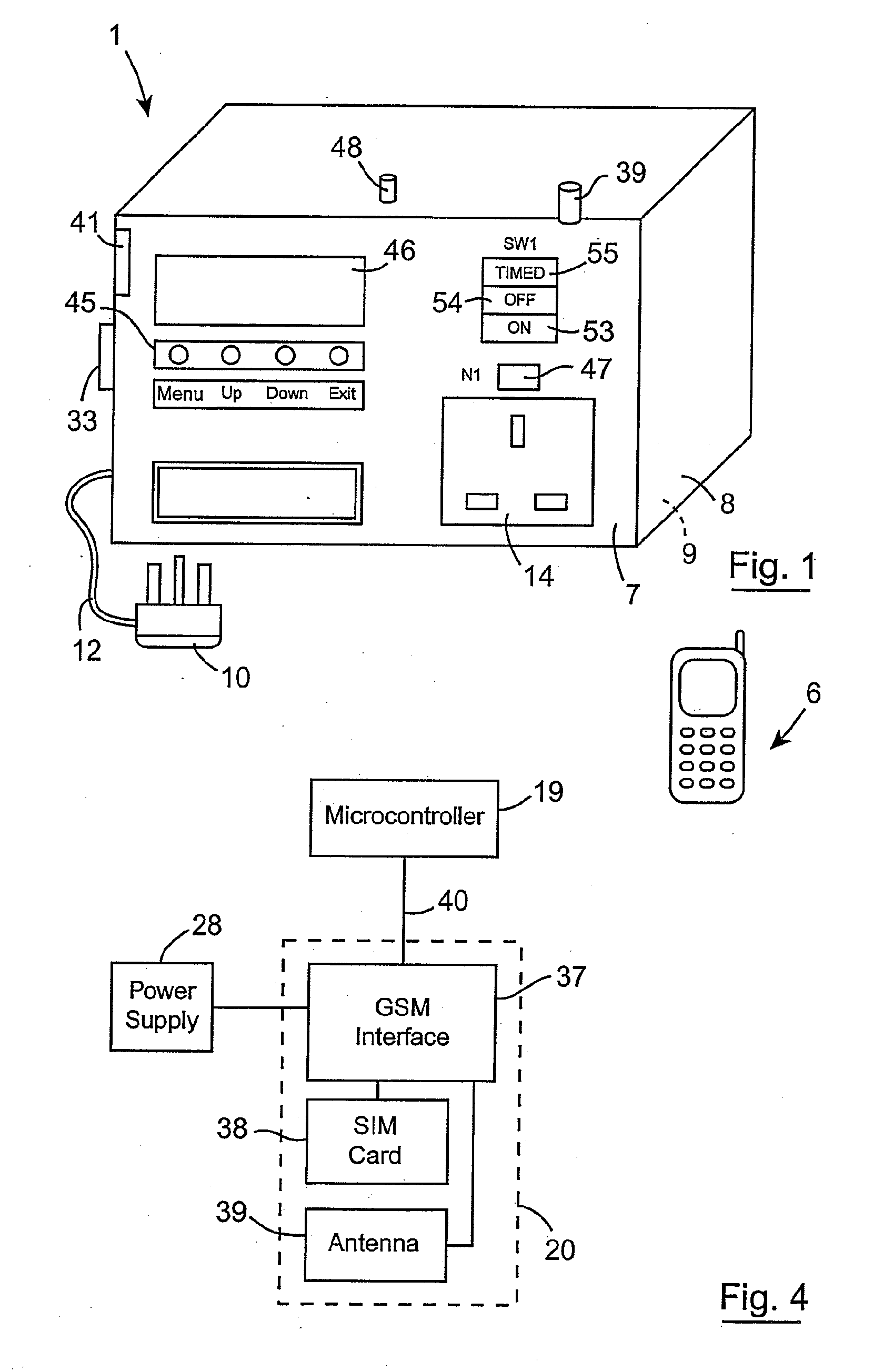
[0079]By providing the communicating means as a communicating circuit suitable for communicating with a cellular telecommunications network, the control apparatus can readily easily be controlled remotely from a cellular phone, and by providing a suitable messaging interface, such as a GSM interface in the communicating circuit, the control apparatus can readily easily be controlled using SMS messaging.
[0080]The provision of the control means as a programmable microcontroller has the advantage that the control apparatus can readily easily be programmed via the communicating means, and indeed, where the communicating means is provided as a communicating circuit suitable for communicating with a cellular telecommunications network, the microcontroller can readily easily be programmed by a remotely located computer also coupled into a cellular telecommunications network.

Problems solved by technology

The operational status of the electrical load may be abnormal as a result of a number of factors.
For example, the electrical load may be faulty, or may have been disconnected from the output means.

Method used


Image

  • Control apparatus
  • Control apparatus
  • Control apparatus

Examples


Embodiment Construction

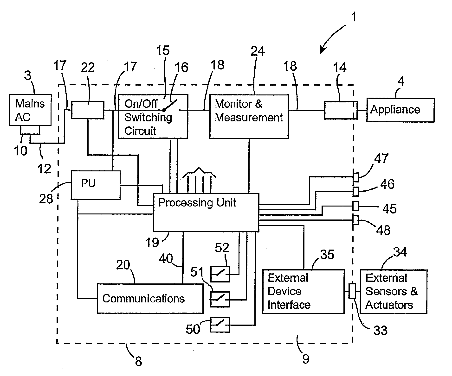
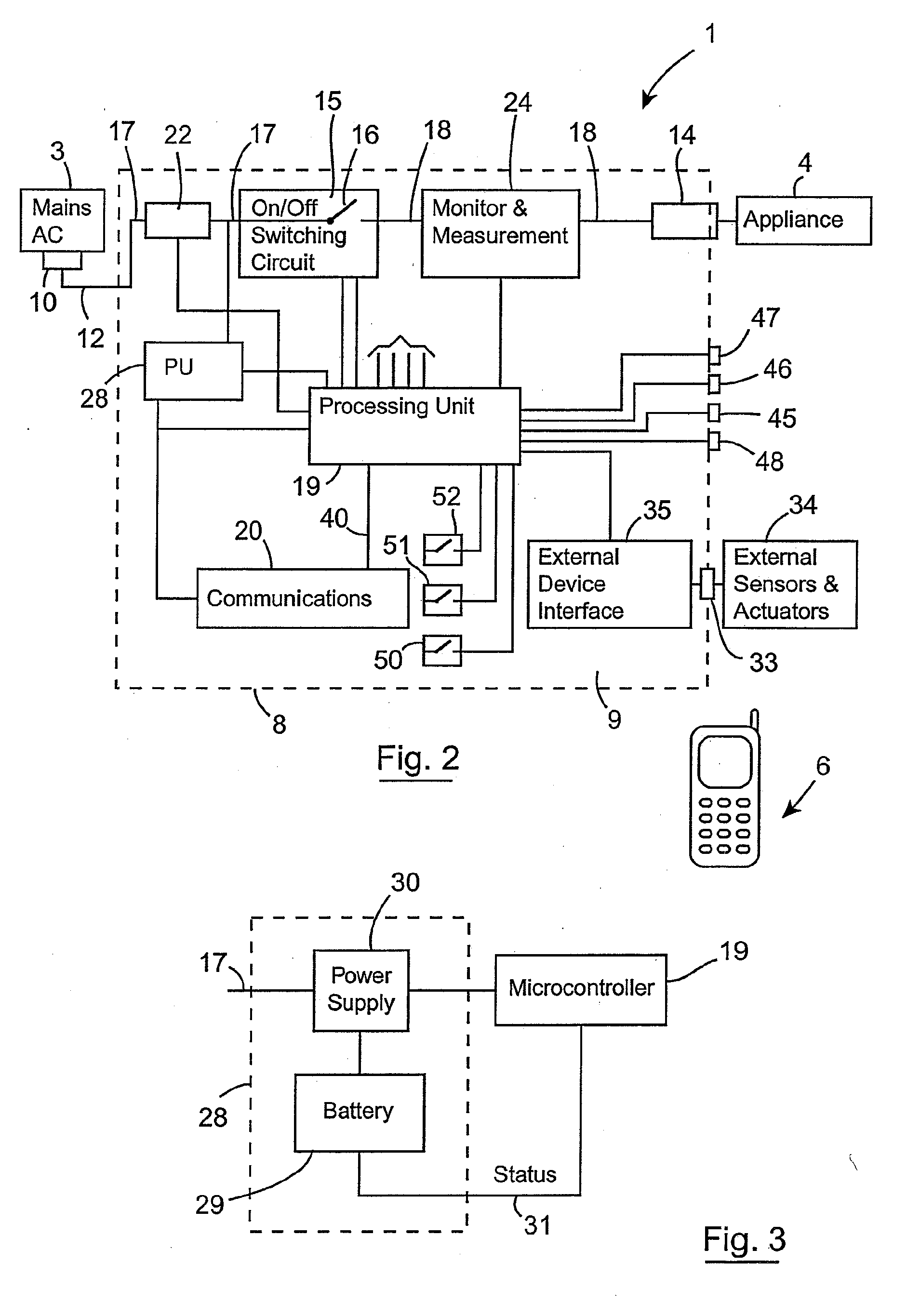
[0092]Referring to the drawings and initially to FIGS. 1 to 4, there is illustrated control apparatus according to the invention, indicated generally by the reference numeral 1, for selectively applying an electrical power supply, namely, a mains AC power supply 3 to an electrical load, for example, an appliance 4, such as a table lamp, a central heating system, a washing machine, or indeed any other appliance. The control apparatus 1 is responsive to a control signal from a remote communications device, in this embodiment of the invention a cellular telephone 6, which transmits the control signal in the form of an SMS message for operating the control apparatus 1 for coupling the appliance 4 to the mains supply 3, or for isolating the appliance 4 from the mains supply 3, as will be described in detail below.

[0093]The control apparatus 1 is provided as a single integral unit comprising a housing 8 having a front panel 7 and defining a hollow interior region 9 within which components...


PUM


Abstract

Control apparatus (1) for selectively applying a mains AC electrical supply (3) to an electrical appliance (4) in response to a remote signal received via a cellular telecommunications network comprises a housing (8) within which an electrical socket (14) for providing power to the appliance (4) is integrally formed. An electrical plug top (10) on a cable (12) extending from the housing (8) is provided for coupling to the mains supply (3). A switch circuit (15) under the control of a microcontroller (19) controls the mains supply (3) to the electrical socket (14). A communications circuit (20) which is adapted for communicating with a cellular telecommunications network receives SMS control messages, and the microcontroller (19) is responsive to the SMS control messages for in turn operating the switch circuit (15) to selectively switch the mains supply (3) to the appliance (4). A power supply circuit (28) independent of the mains supply (3) powers the control apparatus (1). A volt meter (22) monitors the presence of the mains supply (3) and an amp meter (24) monitors the current being drawn by the appliance (4). The microcontroller (19) is responsive to the volt meter (22) detecting the mains supply and the amp meter (24) detecting the absence of current being drawn by the appliance (4) when the switch circuit (15) is in the closed circuit state for determining the operational status of the appliance as faulty.

Description

[0001]This is a Continuation of application Ser. No. 11 / 572,806 filed Jan. 26, 2007, which is a national stage application filed under §371 of PCT Application No. PCT / IE2005 / 000090, published as WO2006 / 025041, filed Sep. 2, 2005, which claims benefit of Irish Patent Application No. S2004 / 0583 filed Sep. 2, 2004, the disclosures of which are incorporated herein by reference in their entirety.BACKGROUND OF THE INVENTION[0002]The present invention relates to control apparatus, and in particular, to a control apparatus for selectively applying an electrical power supply to an electrical load in response to a remotely received signal.[0003]There are many applications where it is desirable, and indeed, in many cases necessary, to be able to selectively apply an electrical power supply, for example, mains electricity, to an electrical load in response to a remotely generated signal. For example, it is desirable to be able to power up a central heating system in a holiday house a few days b...

Claims


Application Information

Patent Timeline
Patent Type & Authority Applications(United States)
IPC IPC(8): H01H47/00
CPCH02J13/001H02J13/0072H04L12/2803H04L12/2818H04L2012/2843H04L2012/285Y04S20/242Y02B90/2646Y04S10/40Y04S20/228Y04S40/125Y02B70/3266Y02B70/325H02J13/00018H02J13/00001Y02B90/20Y04S40/124H01R31/065Y02B70/30Y04S20/20
Inventor RYAN, LIAM ANTHONYEDMONDS, EDWARD JOSEPHCURRAN, JOHN GERARD
Owner RYAN LIAM ANTHONY
Learn More