Clock distributor for use in semiconductor logics for generating clock signals when enabled and a method therefor

a technology of clock distributor and semiconductor logic, which is applied in the direction of generating/distributing signals, pulse techniques, instruments, etc., can solve the problems of approximately ten times the power consumption of the gated clock circuit, or upstream in the signal direction, and achieve the effect of reducing power consumption, reducing power consumption, and reducing power consumption

Active Publication Date: 2009-02-10
LAPIS SEMICON CO LTD
View PDF15 Cites 9 Cited by
  • Summary
  • Abstract
  • Description
  • Claims
  • Application Information

AI Technical Summary

Benefits of technology

[0015]It is an object of the present invention to provide a clock distributor circuit that works with power consumption more effectively reduced for use in semiconductor logic circuitry including a clock synchronous circuit, and a clock distribution method.
[0018]With the clock distributor circuit according to the invention, the clock generator circuits, functioning as generators for generating gated clock signals, are adapted for receiving the enable signal instead of the clock signal. It is therefore possible to reduce the power that would otherwise consumed by toggling the clock signal. In addition, the power consumption encountered ahead, or upstream in the signal direction, of the gated clock circuits was approximately ten times as much as that encountered behind, or downstream in the signal direction, the gated clock circuits. However, considerable reduction of that power can be expected in accordance with the invention.
[0019]Further, in the clock distributor circuit according to the invention, the different clock generator circuits are adapted to receive clock enable signals different from each other. It is thus possible to supply clock enable signals different from each other to the clock synchronous circuits in dependence upon whether or not the clock synchronous circuits is rendered operative. That gives rise to reduction in power consumption which would otherwise be required for toggling the clock signal to be supplied to clock synchronous circuits rendered inoperable.
[0020]Furthermore, in the clock distributor circuit according to the invention, the clock generator circuits are adapted for synchronizing the gated clock signal in response to the gated clock synchronous signal. Even when the clock generator circuits are different in characteristics from each other to cause the periods to differ between the gated clock signals, it is also possible to prevent operational failures otherwise resultant from skew accumulated by repeated clock cycles.

Problems solved by technology

In addition, the power consumption encountered ahead, or upstream in the signal direction, of the gated clock circuits was approximately ten times as much as that encountered behind, or downstream in the signal direction, the gated clock circuits.

Method used


Image

  • Clock distributor for use in semiconductor logics for generating clock signals when enabled and a method therefor
  • Clock distributor for use in semiconductor logics for generating clock signals when enabled and a method therefor
  • Clock distributor for use in semiconductor logics for generating clock signals when enabled and a method therefor

Examples


Embodiment Construction

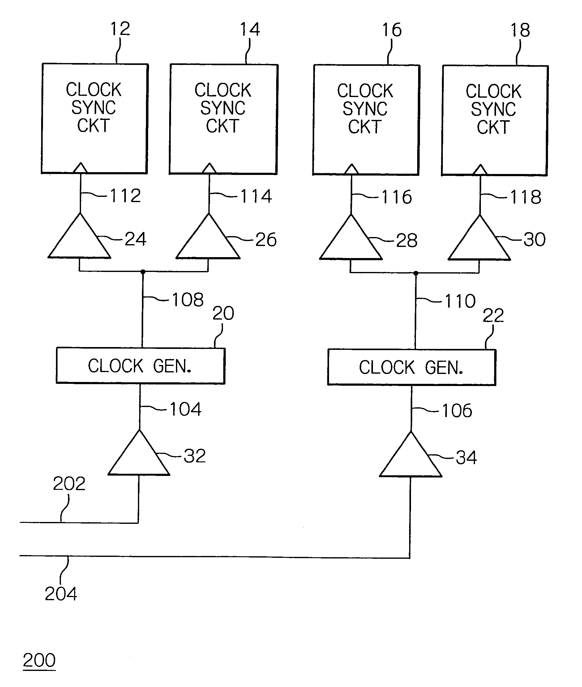
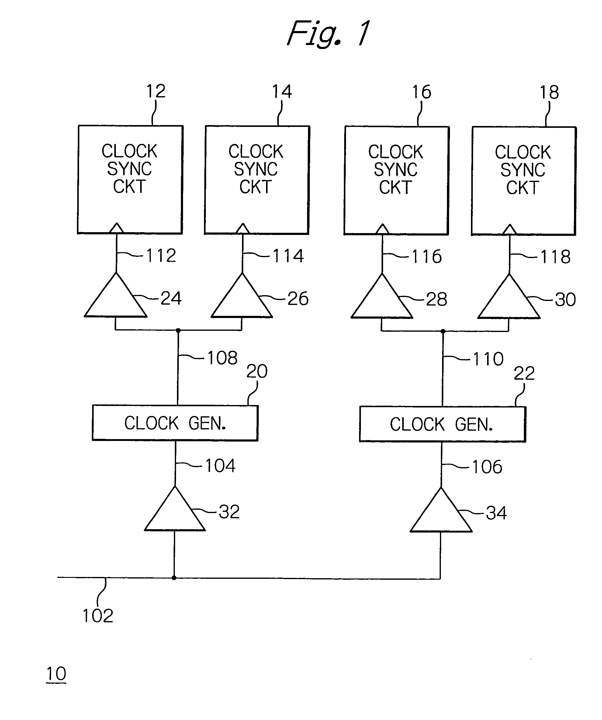
[0032]In the following, the preferred embodiments of the clock distributor circuit according to the invention will be described in detail with reference to the accompanying drawings. As seen from in FIG. 1, for example, the clock distributor circuit 10 includes plural clock generator circuits 20 and 22, and is adapted to control the clock generators 20 and 22 in response to an enable signal 102. The clock generators 20 and 22 are adapted to supply plural clock synchronous circuits 12, 14 and 16, 18 with gated clock signals 108 and 110, respectively. In FIG. 1, the parts or components not directly relating to understanding the invention are not shown for simplification.

[0033]The clock distributor circuit 10 of the embodiment may include more clock synchronous circuits. FIG. 1 shows, however, only four clock synchronous circuits 12, 14, 16 and 18 for simplification. The clock distributor circuit 10 may also comprise more clock generator circuits. Also for simplification, however, only...


PUM


Abstract

A clock distributor circuit is provided which works with power consumption reduced in semiconductor logic circuitry including clock synchronous circuits. The clock distributor circuit includes clock generation circuits generating gated clock signals in response to a clock enable signal to supply clock synchronous circuits with the generated clock signals. It is thus possible to reduce the power that would otherwise consumed by the toggling of the clock signal. A clock distribution method therefore is also provided.

Description

BACKGROUND OF THE INVENTION[0001]1. Field of the Invention[0002]The present invention relates to a clock distributor circuit, and more particularly to a clock distributor circuit that works with power consumption reduced for use in semiconductor logic circuitry including a clock synchronous circuit. The present invention also relates to a method for the same.[0003]2. Description of the Background Art[0004]Conventionally, logic circuits formed by system LSI (Large Scale Integration), such as a central processor unit (CPU) or digital signal processor (DSP), operative in response to a clock signal usually includes a clock synchronous circuit, which may be composed of flip-flop circuits. For those flip-flop circuits, a type of flip-flop circuit may be applicable which has its data input terminal D, clock input terminal C and data output terminal Q and controls clock synchronization in response to a clock signal inputted to the clock input terminal C. This clock signal is applied in comm...

Claims


Application Information

Patent Timeline
Patent Type & Authority Patents(United States)
IPC IPC(8): G06F9/38
CPCG06F1/10G06F1/3203H03K5/135H03K5/1504
Inventor ENDO, NOBUYUKI
Owner LAPIS SEMICON CO LTD
Why Eureka
Try Eureka