
RSSI and ultrasonic based hybrid ranging technology

a hybrid ranging and ultrasonic technology, applied in direction finders, instruments, measurement devices, etc., can solve the problems of consuming more power, consuming more power, and strong directionality, and achieves low speed, strong directionality, and more power consumption.

Active Publication Date: 2010-05-04
PANASONIC CORP
View PDF6 Cites 9 Cited by
  • Summary
  • Abstract
  • Description
  • Claims
  • Application Information

AI Technical Summary

Benefits of technology

[0017]In view of the problems above described, the present invention is done. The present invention can overcome the drawbacks of the existing technologies, that is, multi-path effects, NLOS, strong directionality, low speed and more power consumption, so as to meet various demand from monitoring and controlling applications.
[0020]With the methods of the invention, the following technical effects can be obtained:
[0021]a) the hybrid ranging method can decrease the interference from the directionality in the ultrasonic ranging process;
[0022]b) the power consumption due to frequently transmission of ultrasonic signals is decreased;
[0023]c) the measuring speed is enhanced by intermittently using RSSI based measuring method to meet the demand of moving measurement.
[0024]d) the effects from the change of the environment is decreased by using ultrasonic ranging method;

Problems solved by technology

The TDOA based technology has an advantage of high accuracy, but has a disadvantage of strong directionality and needs to perform ultrasonic communication frequently, that is, consuming more power.
Thus, the more power will be consumed.
Meanwhile, the measured results are not so accurate when the nodes are not in the direction of ultrasonic wave because the transmission of ultrasonic wave has a strong directionality.
The drawback of the method lies in that the update of the database is difficult when the environment is changed.

Method used


Image

  • RSSI and ultrasonic based hybrid ranging technology
  • RSSI and ultrasonic based hybrid ranging technology
  • RSSI and ultrasonic based hybrid ranging technology

Examples


Embodiment Construction

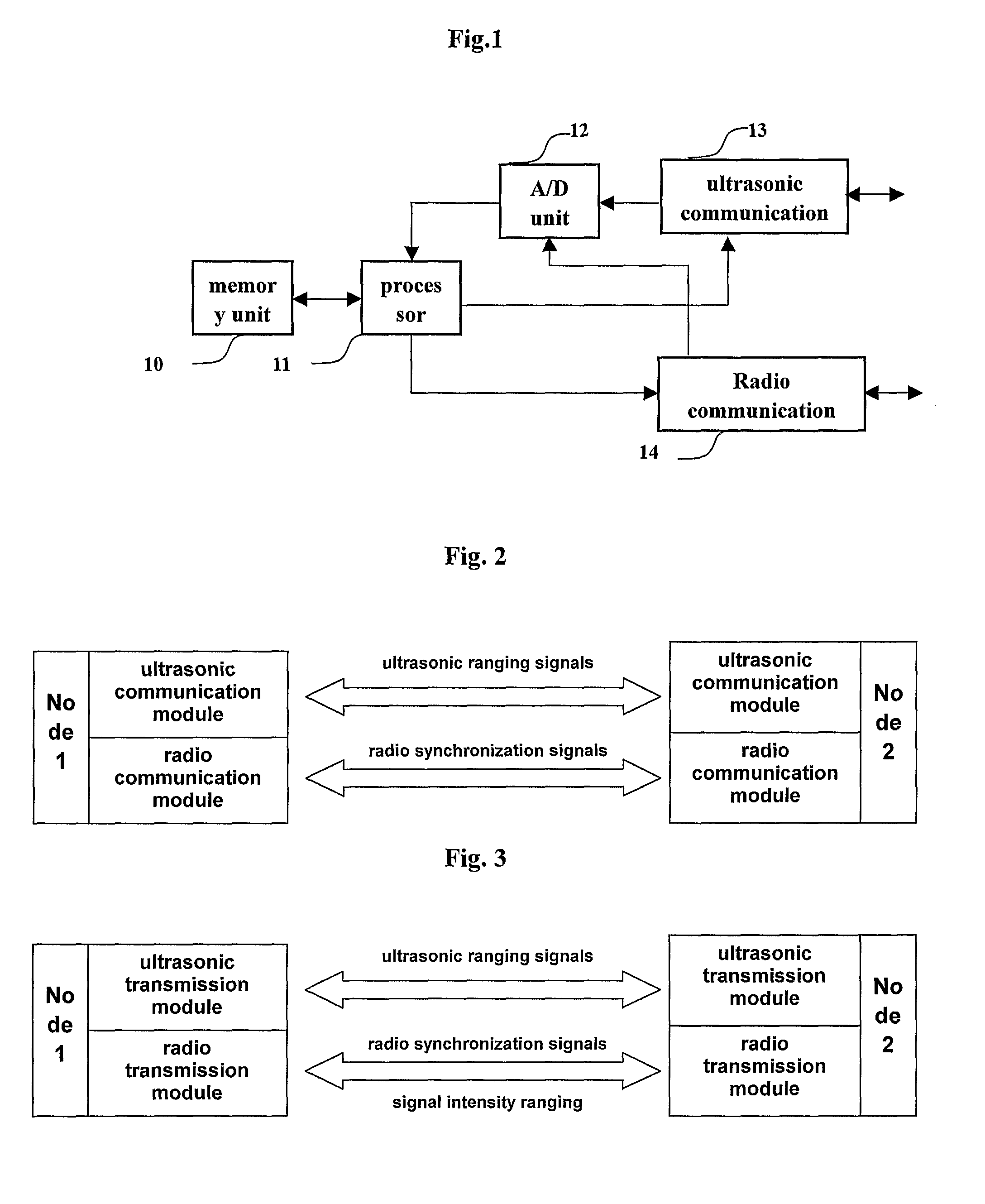
[0034]The hybrid ranging method combining ultrasonic ranging and radio ranging according to the present invention will be described below by way of preferred embodiments with reference to the drawings. FIG. 3 depicts a diagram of the ranging system according to an embodiment of the present invention.

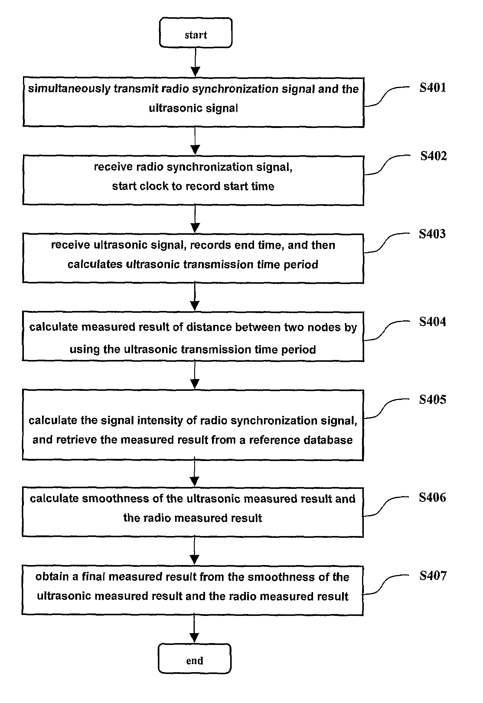
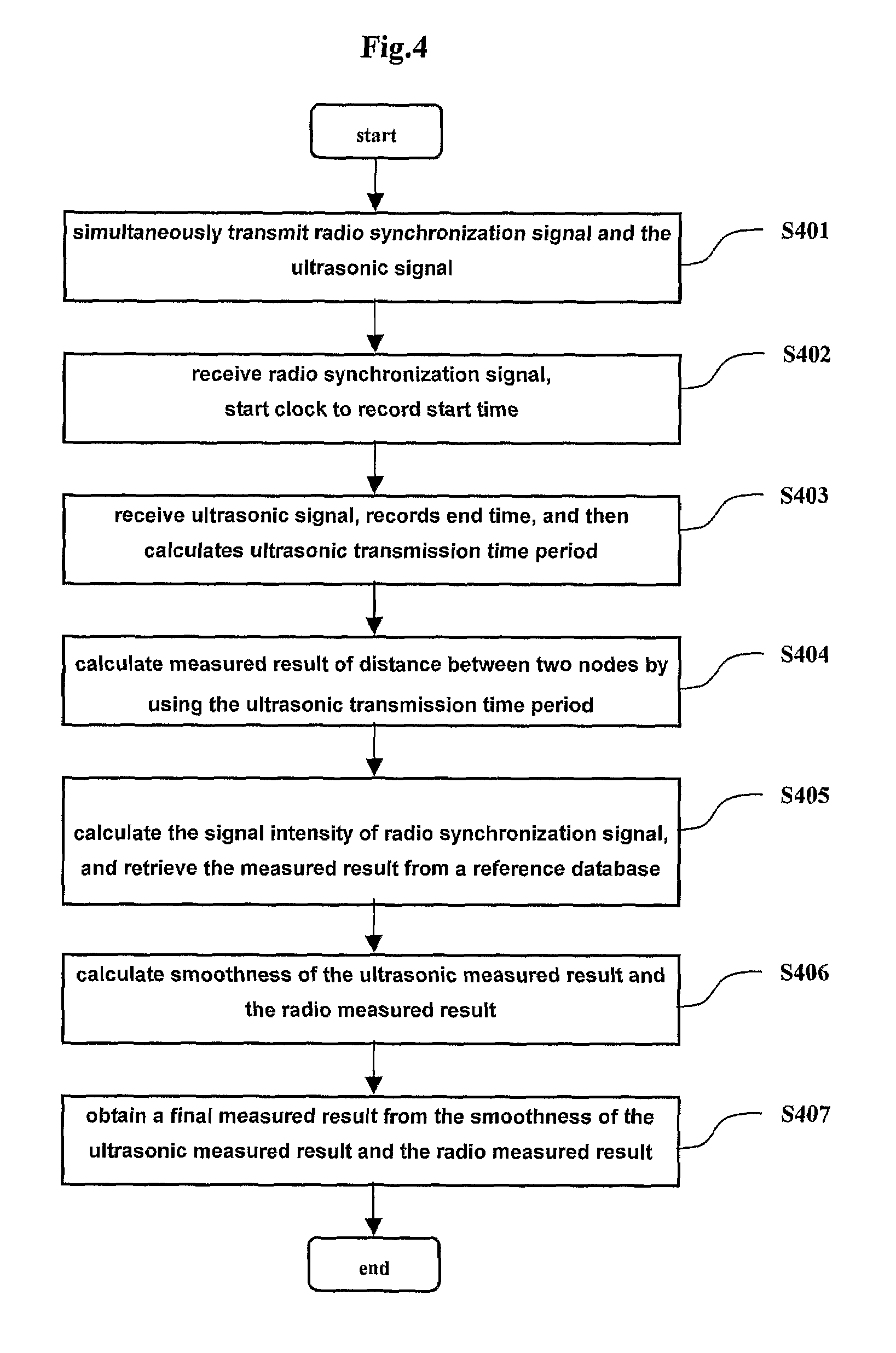
[0035]While a node 1 is transmitting radio synchronization signal, an intensity of the radio signal is measured, and the measured result is used as a data source in order to calculate a distance between two nodes by using the radio intensity ranging principle. Thereafter, another distance is calculated by a detected ultrasonic signal. After obtaining these two measured results, an actual distance is determined by error analyzing and statistical methods. The detailed flowchart is shown in FIG. 4.

[0036]In FIG. 4, the following steps are performed.

[0037]S401: a node 1 simultaneously transmits a radio synchronization signal and an ultrasonic signal;

[0038]S402: a node 2 receives the radio syn...


PUM


Abstract

Disclosed is a hybrid ranging method comprising the steps of: transmitting from a first node an ultrasonic signal and a radio signal comprising at least one radio synchronization signal with a predetermined ratio; calculating, at a second node, a ultrasonic transmission time period between the receipt of the radio synchronization signal and the receipt of the ultrasonic signal; calculating, at the second node, an ultrasonic measured result between the first node and the second node by using the ultrasonic transmission time period; calculating, at the second node, the strength of the received radio signal, and obtaining a radio measured result between the first node and the second node from a reference database; calculating, at the second node, the smoothness of the ultrasonic measured result and the radio measured result; and determining at the second node, a final measured result according to the smoothness of the ultrasonic measured result and the radio measured result.

Description

FIELD OF THE INVENTION[0001]The present invention relates to a wireless ranging method for accurately and quickly measuring distance indoor, which can be used for localizing nodes by measuring the distance between nodes, particularly, to a ranging technology combining the RSSI based ranging and TDOA based ranging technologies which is capable of improving measuring speed and accuracy of the wireless ranging indoor.PRIOR ARTS RELATED TO THE INVENTION[0002]The technology of localization indoor, which is an effective monitoring and controlling technology, has been widely used in the various aspects. With the developing of the micro-electromechanical technology and wireless network technology, it is possible to arrange localization network to obtain position of devices to be applied a new service. As the popularizing of various applications of the localization system, further demands for the performances thereof occur. These demands greatly prompt the development of the accurate, quick ...

Claims


Application Information

Patent Timeline
Patent Type & Authority Patents(United States)
IPC IPC(8): G01S5/00G01S5/02
CPCG01S5/0252G01S11/14G01S11/06G01S5/18
Inventor WEI, QIANGYU, XUWEN
Owner PANASONIC CORP
Learn More