Display system with LED backlight means

a backlighting and display system technology, applied in the field of display systems, can solve the problems of high power consumption of backlight sources, low power utilization efficiency, high voltage risk, etc., and achieve the effect of avoiding high voltage risk and saving power consumption

Inactive Publication Date: 2009-10-15
CHI RUEI TSAI
View PDF5 Cites 10 Cited by
  • Summary
  • Abstract
  • Description
  • Claims
  • Application Information

AI Technical Summary

Benefits of technology

[0007]The present invention has been accomplished under the circumstances in view. It is therefore the main object of the present invention to provide a display system with LED backlight means, which saves much power consumption and avoids a high voltage risk.

Problems solved by technology

However, a high power backlight source consumes much power supply.
The booster circuit design lowers the power utilization efficiency, and has a high voltage risk.

Method used


Image

  • Display system with LED backlight means
  • Display system with LED backlight means
  • Display system with LED backlight means

Examples


example i

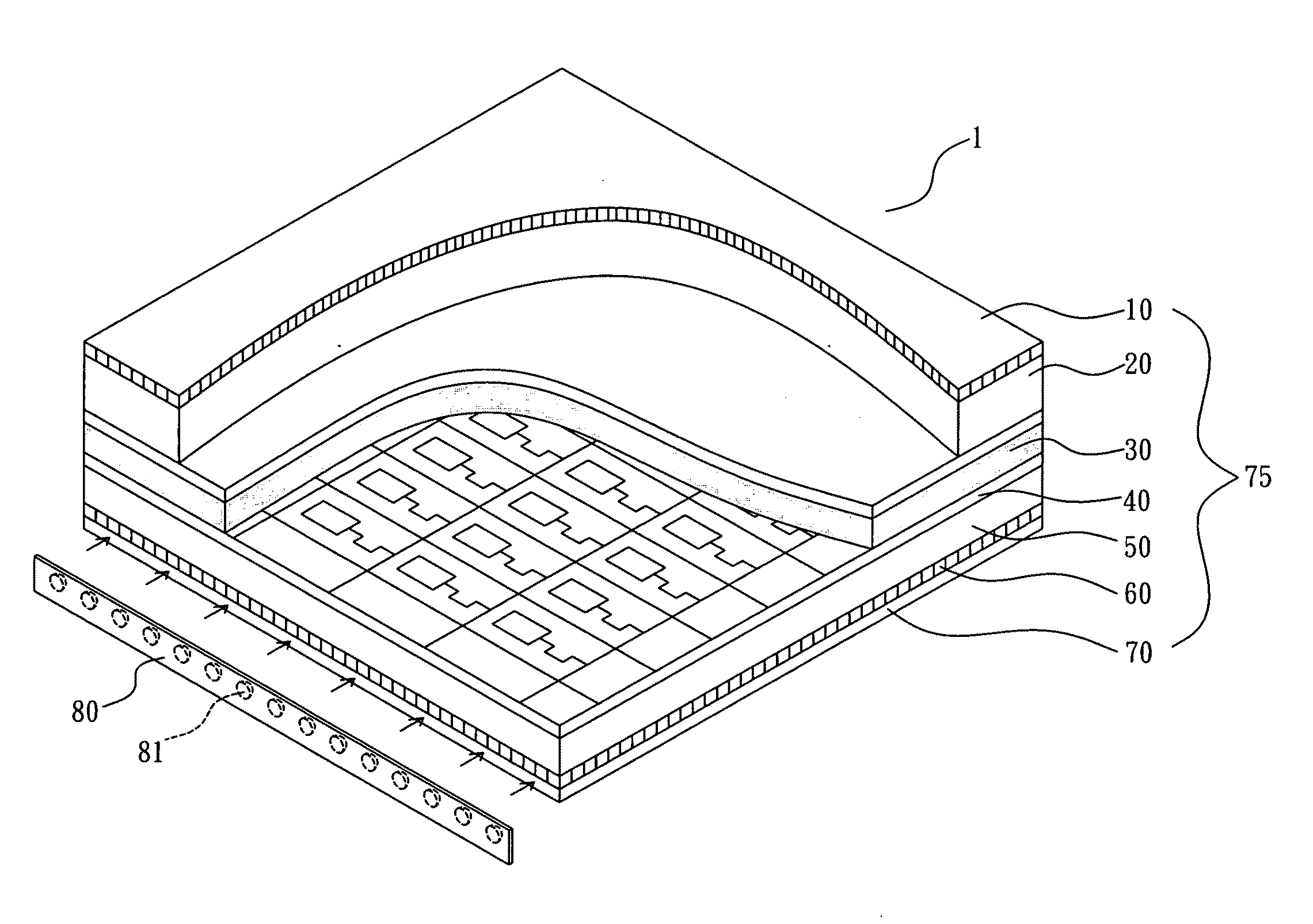
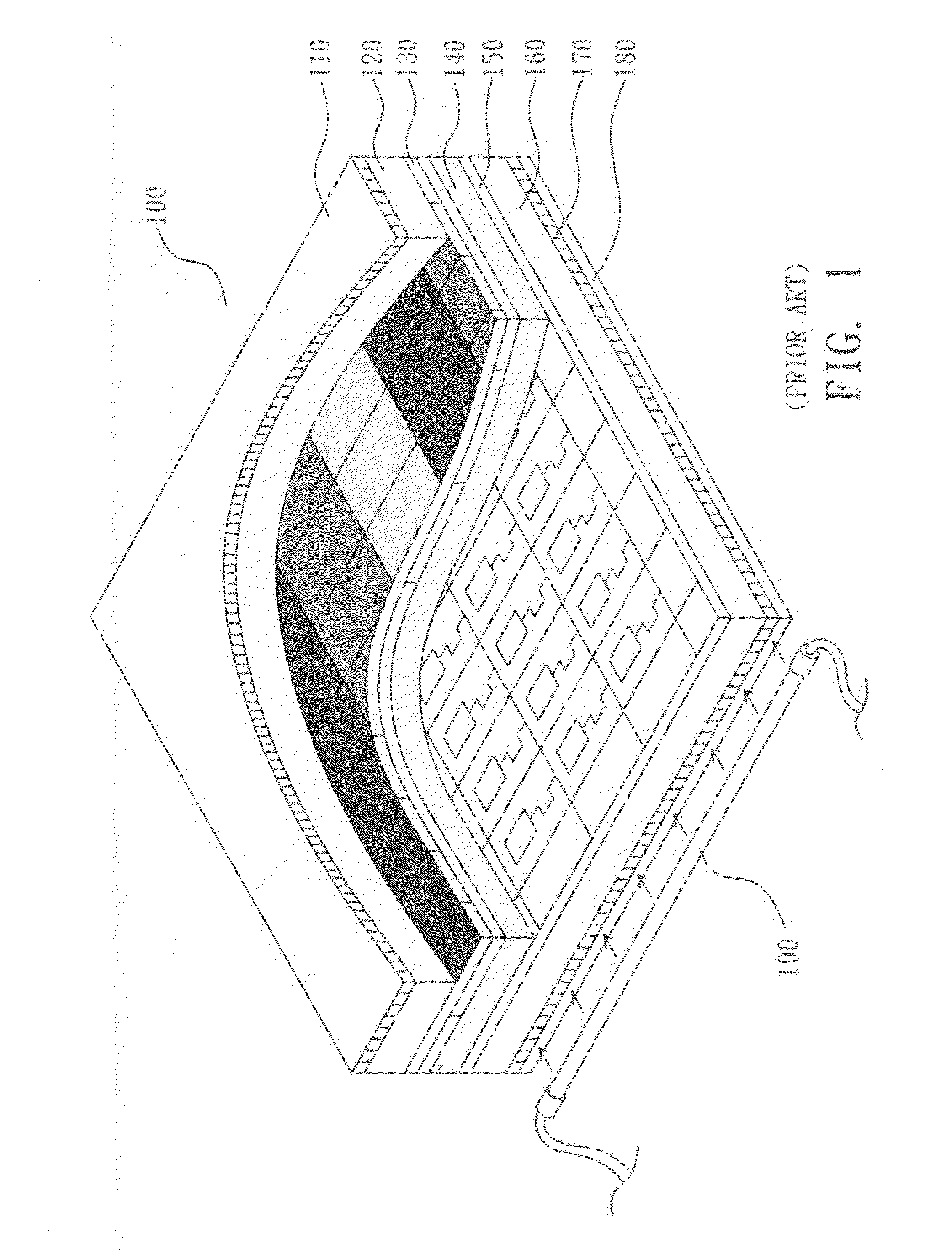
[0027]The backlight set is assembled with the color LCD panel 100 shown in FIG. 1 to form a display system. The color LCD panel 100 comprises a color filter 130. Under the consideration of transmittancy (light energy utilization efficiency), the red, green, and blue transmissive wavelength is limited to a certain range, for example, 50 nm or more. However, the light emitted by each LED 81 is a single color of which the half-wave width is about 30 nm on blue color, or about 25 nm on red color. Therefore, it shows excellent effect on every color, and the single color light emitted by every LED 81 can go through the color filter completely. Therefore, the color LCD panel 100 needs light energy only about ⅓ or less when compared to the prior art design, saving much power consumption.

example ii

[0028]The backlight set is assembled with a regular color LCD panel similar to that shown in FIG. 1 with the exception that the aforesaid color filter 130 is eliminated and each pixel is divided into R, G. and B zones. Similar to the aforesaid first example, this second example saves much power consumption. Further, because this second example eliminates the color filter 130, the cost of the display system is greatly reduced (the cost of a color filter is about 26% in a 15″ color LCD panel).

example iii

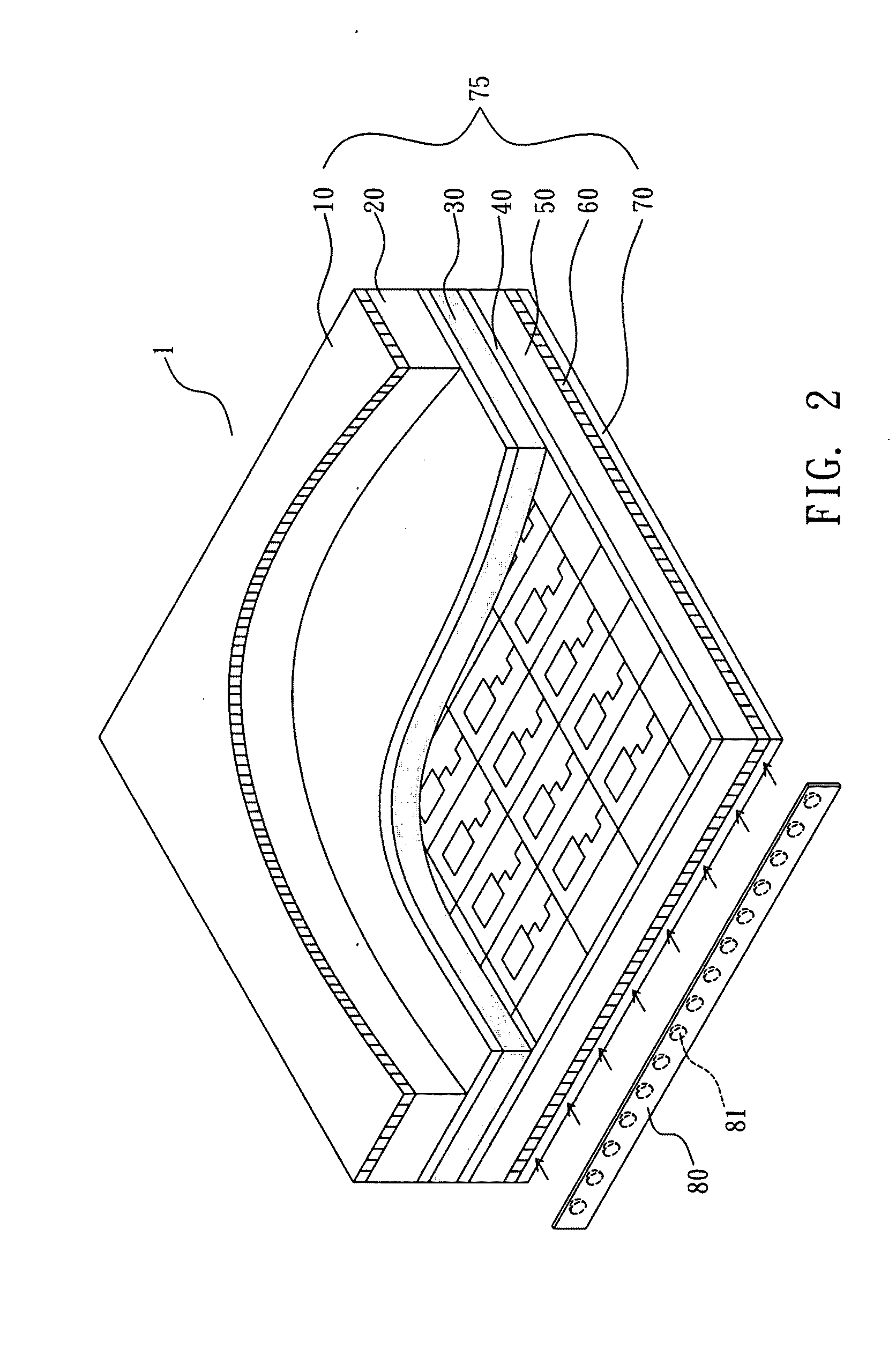
[0029]The backlight set is assembled with a monochrome (black-and-white) gray-tone LCD panel to form a display system, reducing much the cost. Under a same size and same resolution, every single pixel in a monochrome gray-tone LCD panel 75 is one single zone not to be divided into RGB three zones. Therefore, the circuit layout is simplified, and the pixel aperture area is tripled or more when compared with a regular color LCD panel, i.e., the transmittancy is about triple or more of that of a regular color LCD panel. Therefore, a display system made according to this third example requires light energy about (⅓)×(⅓)= 1 / 9 or less when compared to an equivalent color LCD system, saving much power consumption. When displaying a color image through a conventional color LCD panel, the images of RGB three prime colors may be dislocated. In a monochrome gray-tome LCD panel, RGB three prime colors are from the same location. Therefore this third example avoids image dislocation, and the mix...


PUM


Abstract

A power-saving display system without color filter is disclosed to include a backlight panel, a LED backlight set controlled to emit a first light source, a second light source, and/or a third light source to the backlight panel, a LCD panel disposed at a top side of said backlight panel, and a video signal controller controlled to output a first monochrome video image, a second monochrome video image, and/or a third monochrome video image to the LCD panel for synthesizing into a color video image for display on the LCD panel.

Description

BACKGROUND OF THE INVENTION[0001]1. Field of the Invention[0002]The present invention relates to a display system and more particularly, to a power-saving, non-color filter type display system composed of a LED backlight set and a monochrome gray-tone LCD panel for displaying color video images.[0003]2. Description of the Related Art[0004]FIG. 1 illustrates the structure of a conventional color LCD panel. The color LCD panel 100 comprises an upper polarizer 110, an upper glass substrate 120, a color filter 130, a liquid crystal layer 140, a thin-film substrate 150, a lower glass substrate 160, a lower polarizer 170, a backlight panel 180, and a backlight source 190. This design uses a cold cathode fluorescent lamp (CCFL) for the backlight source 190. The backlight source 190 is disposed at one peripheral side of the backlight panel 180. During operation of the color LCD panel 100, white light from the backlight source 190 goes through the lower polarizer 170, and is then twisted 90 ...

Claims


Application Information

Patent Timeline
Patent Type & Authority Applications(United States)
IPC IPC(8): G09G3/36
CPCG09G3/3426G09G2330/021G09G2310/0235
Inventor NAUM, SOSHCHINLO, WEI-HUNGTSAI, CHI-RUEI
Owner CHI RUEI TSAI
Why Eureka
Try Eureka