
Flat panel display and backlight module thereof

a flat panel display and backlight module technology, applied in the field of backlight modules, can solve the problems of phosphorous sludge not evenly distributed over the whole inner surface of the vacuum tube, unable to reduce the size of illuminated lcds, and gradual loss of visible ligh

Inactive Publication Date: 2009-09-17
KISMART
View PDF2 Cites 114 Cited by
  • Summary
  • Abstract
  • Description
  • Claims
  • Application Information

AI Technical Summary

Benefits of technology

[0012]According to a second aspect of the present invention, a backlight module provides uniform illumination for each screen or each position on one screen.

Problems solved by technology

However, the phosphorous sludge is not evenly distributed over the whole inner surface of the vacuum tube, let alone to distribute the phosphorous sludge in a large CCFL vacuum tube.
However, if the space between the panel and the illuminant is not narrowed down properly, beam interference and reflection occur and thus amplifies the luminance differentials.
Nevertheless, the visible light will be lost gradually due to being blocked by optical plates (e.g., diffusion plate) therein.
Because the “Mura Effect” of CCFL illuminated LCDs degrades the illumination quality and cannot be resolved, CCFL illuminated LCDs cannot be downsized and therefore become less competitive in the commercial market.

Method used


Image

  • Flat panel display and backlight module thereof
  • Flat panel display and backlight module thereof
  • Flat panel display and backlight module thereof

Examples


first embodiment

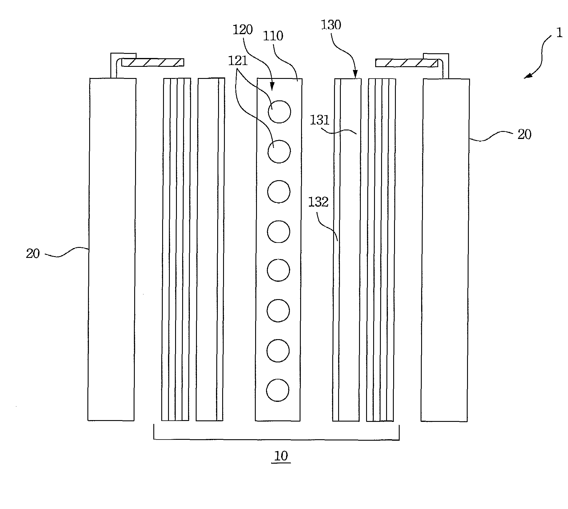
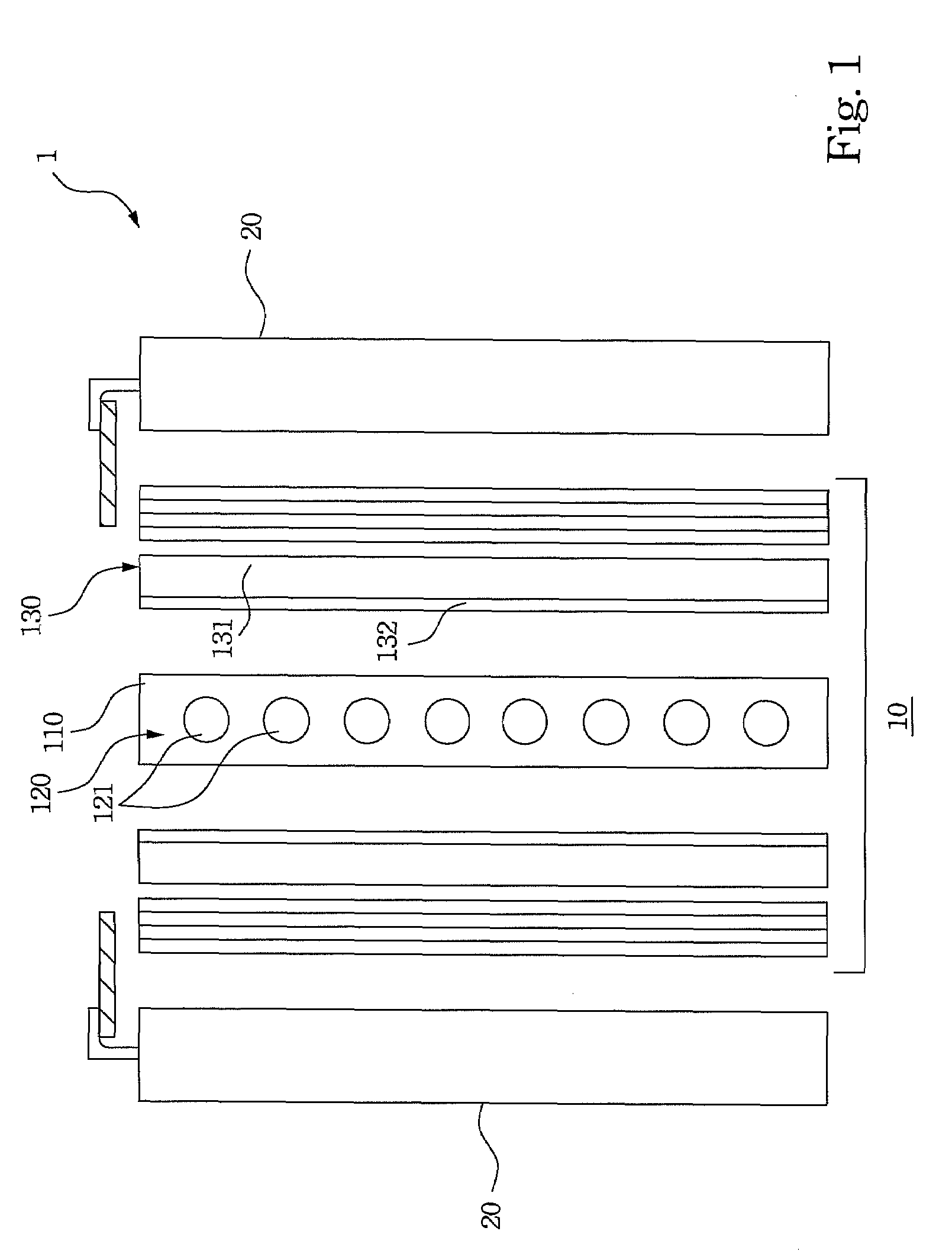
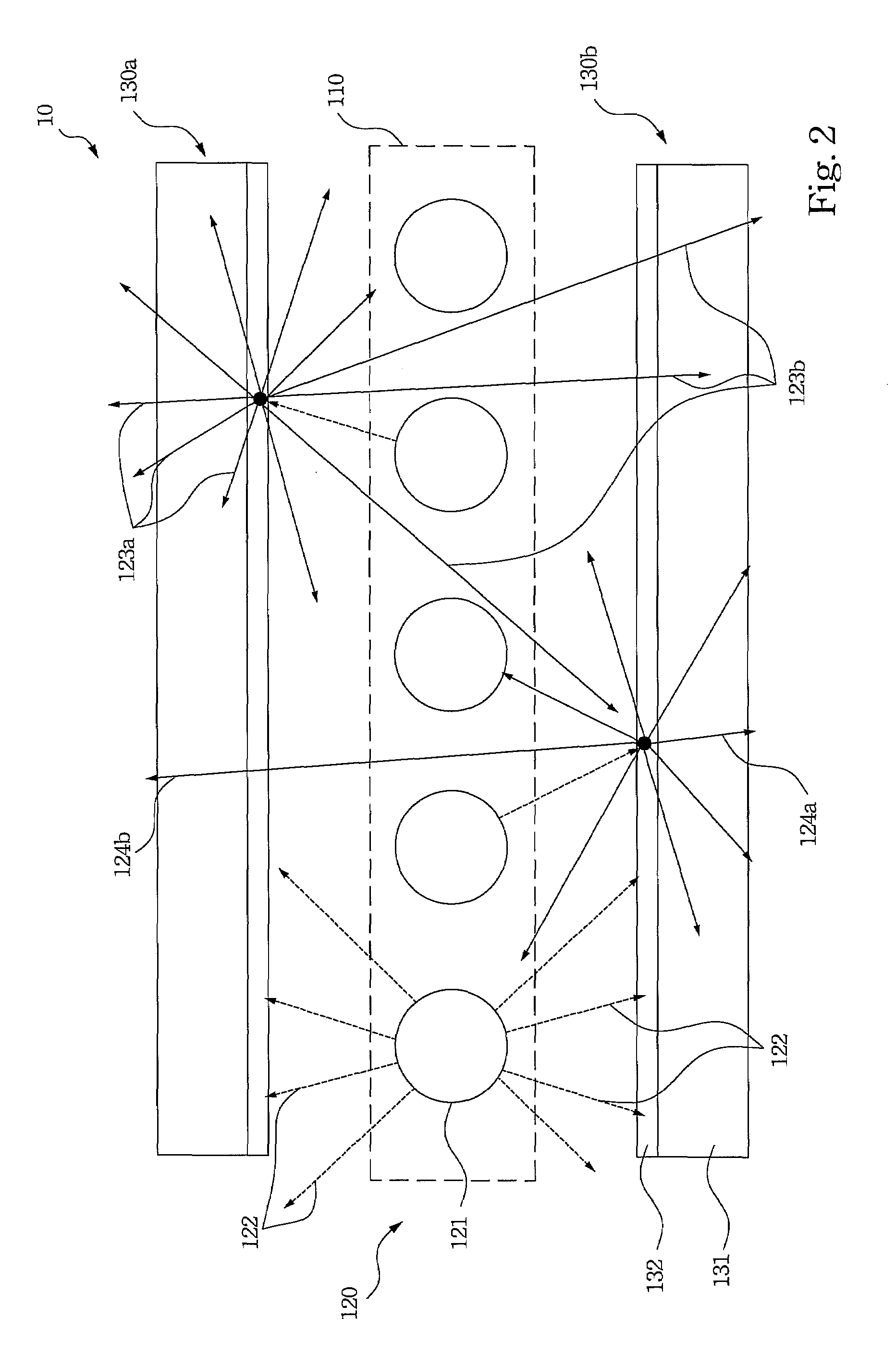
[0038]In the first embodiment, if the wavelength converters 130 such as top and bottom wavelength converters 130a, 130b shown in FIG. 2, are plural, the UVC lamps transmit the ultraviolet light 122 radially to the top and bottom wavelength converters 130a, 130b respectively. The top and bottom wavelength converters 130a, 130b can be either flat or flexible depending on the figure or the screen numbers of the flat panel display 1. The top and bottom wavelength converters 130a, 130b are positioned near the lamp holder 110 and the UVC lamps.

[0039]After the ultraviolet light arrives at the top wavelength converter 130a, the converting layer 132 of the top wavelength converter 130a converts the ultraviolet light (i.e. the light 122) into light with an aimed optical wavelength (i.e. light 123a and 123b with a second wavelength in FIG. 2) and radially emits the ultraviolet light (i.e. the light 122) respectively. Note that a portion of the light with aimed optical wavelength (i.e. the port...

second embodiment

[0059]After the UVC lamps in the second embodiment radially emit the ultraviolet light (refer to light 122 with a first wavelength in FIG. 8) to the wavelength converter 130′ individually, the converting layer 132′ of the wavelength converter 130′ converts the ultraviolet light (i.e. light 122 in FIG. 8) into light with the aimed optical wavelength (refer to lights 123c and 123d with a second wavelength in FIG. 8).

[0060]Note that a portion of the light with the aimed optical wavelength (i.e. the portion light 123c) will be emitted outward directly from a position of the wavelength converter 130′, and the other portion of the light with the aimed optical wavelength (i.e. the light 123d in FIG. 8) will be radially emitted from the position thereof to the other positions of the wavelength converter 130′. When the other portion of the light with the aimed optical wavelength (i.e. the light 123d in FIG. 8) arrives at the other positions thereof, the other portion of the light with the ai...


PUM


Abstract

The invention is related to a flat panel display and a backlight module thereof. The backlight module comprises a light source and a plurality of wavelength converters. The light source formed by some arranged luminous elements would radially emit light with an optical wavelength individually. These wavelength converters are near the light source and convert the light with the wavelength. The converted light with another wavelength is radially emitted, in which a portion of the converted light with another wavelength is emitted outward directly from the wavelength converter, while the other portion thereof is emitted from the wavelength converter toward the other wavelength converters.

Description

RELATED APPLICATIONS[0001]This application claims priority to Taiwan Application Serial Number 97108904, filed Mar. 13, 2008, which is herein incorporated by reference.BACKGROUND[0002]1. Field of Invention[0003]This invention is related to a backlight module, and more particularly to a backlight module of a flat panel display for providing multiple viewing aspects.[0004]2. Description of Related Art[0005]An illuminant of a traditional backlight module of the Liquid Crystal Display (LCD) provides visible light thereof. Normally, the illuminants can be Cold Cathode Fluorescent Lamps (CCFL), External Electrode Fluorescent Lamps (EEFL), Light Emitting Diodes (LED), Carbon Nanotubes (CNT), Flat Fluorescent Lamps (FFL) or Organic Light Emitting Displays (OLED).[0006]For example, the CCFL is made by first applying a phosphor layer (e.g. phosphorous sludge) on an inner surface of a vacuum tube thereof; then, filling a small amount of inert gas and mercury vapor into the vacuum tube and seal...

Claims


Application Information

Patent Timeline
IPC IPC(8): F21V9/16
CPCG09F13/04G09F9/30
Inventor HSIAO, CHUN-CHUNGPENG, YI-SINGCHEN, SUNG-POHUANG, HSIN-TAO
Owner KISMART
Learn More