Leakage signal cancellation apparatus

a leakage signal and apparatus technology, applied in the direction of amplitude demodulation, near-field systems using receivers, line-faults/interference reduction, etc., can solve the problems of expensive quadrature mixers that cannot withstand an input with large signal power, and cannot perform stable cancellation of leakage signals

Inactive Publication Date: 2009-09-17
MITSUBISHI ELECTRIC CORP
View PDF4 Cites 48 Cited by
  • Summary
  • Abstract
  • Description
  • Claims
  • Application Information

AI Technical Summary

Benefits of technology

[0010]Therefore, the leakage signal cancellation apparatus can acquire the cancel signal certainly, and can implement the cancellation of the leakage signal with stability while following variations in the leakage signal.

Problems solved by technology

A problem with the conventional leakage signal cancellation circuit shown in patent reference 1 is that because its mechanism for adjusting the signal divided from the transmitter in such a manner that the signal has the same amplitude as the leakage signal and is in opposite phase with the leakage signal is semifixed, the conventional leakage signal cancellation circuit cannot follow variations in the amplitude and phase of the leakage signal which are caused by change in the surrounding environments of the antenna and therefore cannot perform stable cancellation of the leakage signal.
However, such a circuit needs to make the leakage signal certainly pass through a quadrature mixer in order to acquire a cancel signal.
A problem with the structure shown in nonpatent reference 1 is therefore that because the feedback control works and a large leakage signal is inputted to the quadrature mixer during operation until the leakage signal is sufficiently canceled out, an expensive quadrature mixer which can withstand an input with large signal power must be used as the mixer.

Method used


Image

  • Leakage signal cancellation apparatus
  • Leakage signal cancellation apparatus
  • Leakage signal cancellation apparatus

Examples


embodiment 1

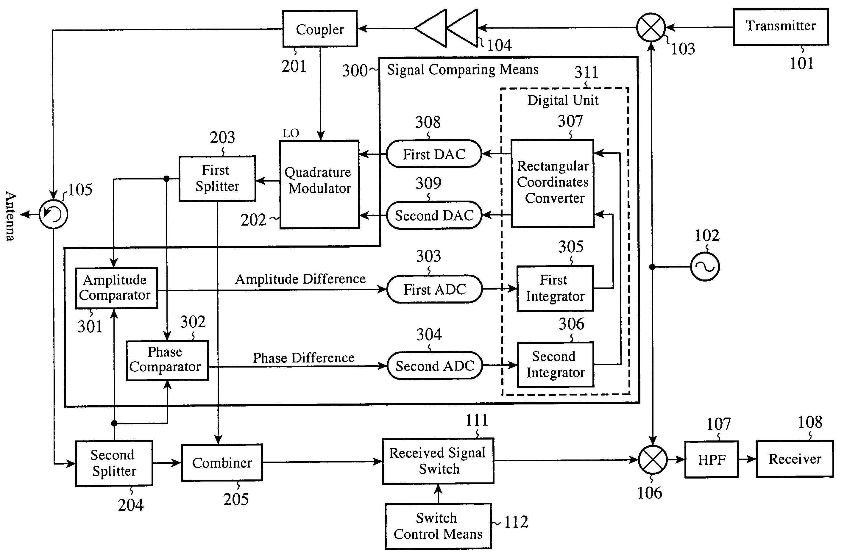
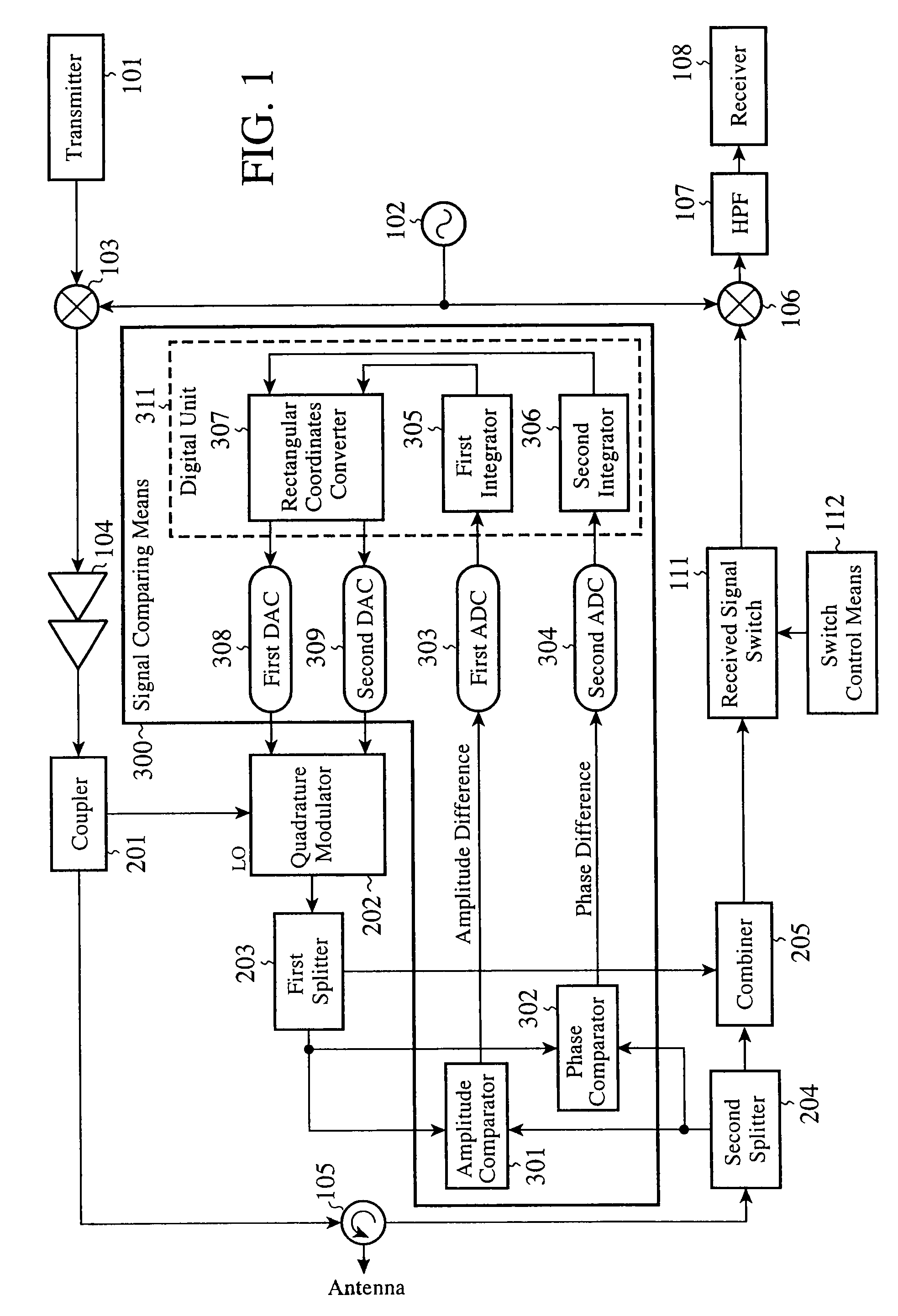
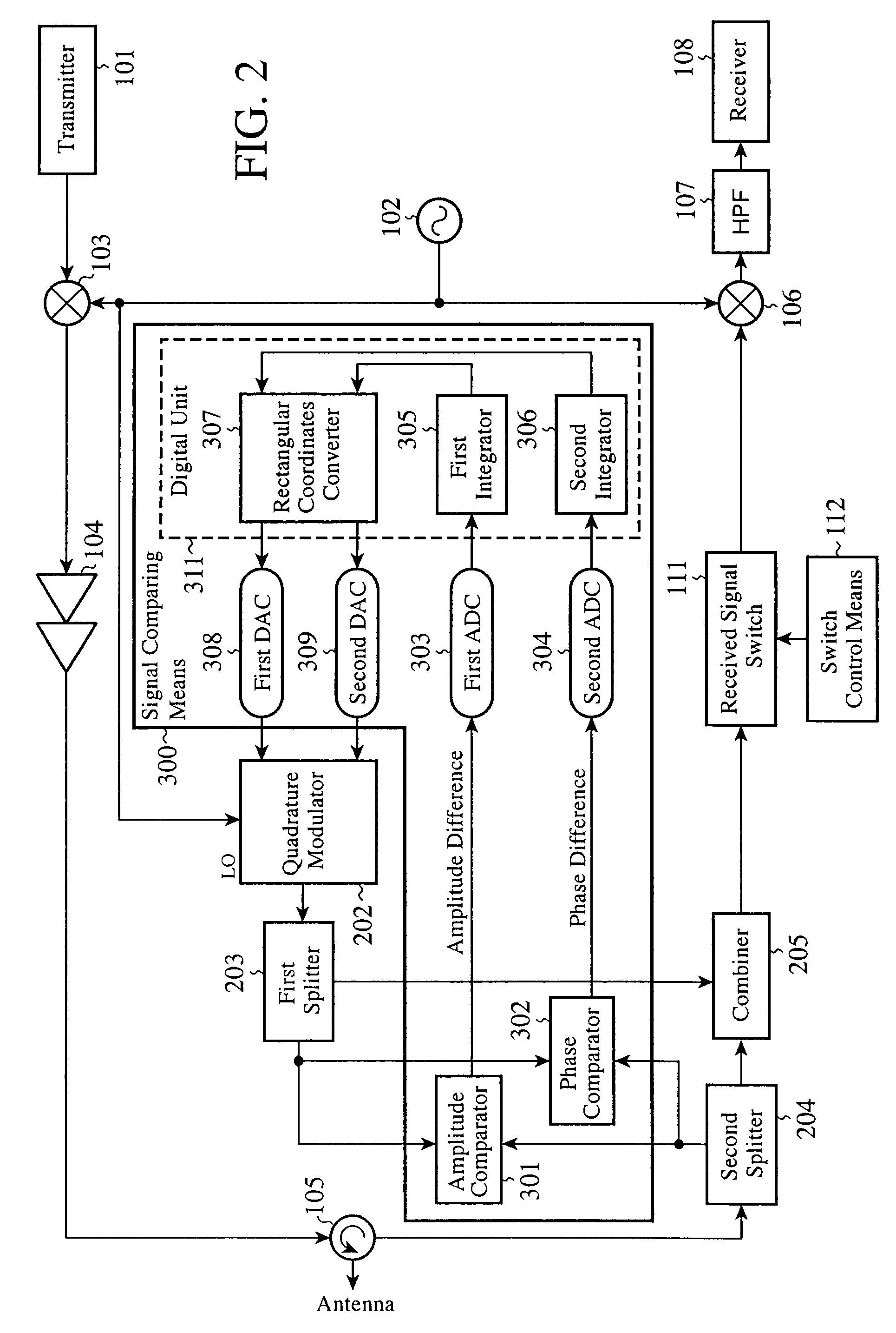
[0020]FIG. 1 is a block diagram showing a transceiver provided with a leakage signal cancellation apparatus in accordance with Embodiment 1 of the present invention.

[0021]The transceiver shown is provided with a transmitter101, a local oscillator 102, a first mixer 103, a power amplifier 104, a circulator 105, a second mixer 106, a high pass filter (HPF) 107, a receiver 108, a coupler 201, a quadrature modulator 202, a first splitter 203, a second splitter 204, a combiner 205, an amplitude comparator 301, a phase comparator 302, a first A / D converter (a first ADC) 303, a second A / D converter (a second ADC) 304, a first integrator 305, a second integrator 306, a rectangular coordinates converter 307, a first D / A converter (a first DAC) 308, a second D / A converter (a second DAC) 309, a received signal switch 111, and a switch control means 112.

[0022]The first integrator 305 through the rectangular coordinates converter 307 are a digital unit 311 for processing a digital signal, and a ...

embodiment 2

[0047]In above-mentioned Embodiment 1, the amplitude and phase of a part of the transmitted signal which is divided by the coupler 201 are led to the LO input of the quadrature modulator 202, and the transmitted signal is adjusted in such a manner as to have the same amplitude as the received signal and to be in phase with the received signal. The quadrature modulator is generally comprised of a mixer. Under the conditions that the voltages of I and Q signals which are inputted to the quadrature modulator are fixed, there is a nonlinear relation between the level of the signal led to the LO input and that of the output signal of the quadrature modulator, and therefore, when the level of the signal led to the LO input is less than a level required for the operation of the mixer, the quadrature modulator stops running. Because the quadrature modulator has such a characteristic, when the interrogator transmits an amplitude-modulated signal or an on / off modulated signal, for either a sy...

embodiment 3

[0051]In above-mentioned Embodiment 1, the amplitude and phase of a part of the transmitted signal which is divided by the coupler 201 are led to the LO input of the quadrature modulator 202, and the transmitted signal is adjusted in such a manner as to have the same amplitude as the received signal and to be in phase with the received signal. As mentioned above, the quadrature modulator is generally comprised of a mixer, and therefore, when the level of a signal inputted to the LO input is less than a level required for the operation of the mixer, the quadrature modulator stops running. Therefore, in a case in which the interrogator transmits an amplitude-modulated signal or an on / off modulated signal, there arises a problem that the leakage signal cannot be sufficiently canceled out.

[0052]From this point of view, in accordance with Embodiment 3, the switch control means 112 carries out a control operation to turn off the received signal switch 111 while in the RFID system the inte...


PUM


Abstract

A quadrature modulator divides a part of a transmitted signal to generate a cancel signal. A signal comparator compares the amplitude and phase of the cancel signal which is generated by the quadrature modulator with those of a received signal, and outputs signals corresponding to the comparison results to the quadrature modulator. The quadrature modulator generates the cancel signal on the basis of the output signals of the signal comparator, and these components perform feedback control such that the cancel signal has the same amplitude as the leakage signal and is in phase with the leakage signal. A combiner combines the cancel signal with an antiphase cancel signal, which is made to be in opposite phase with the cancel signal outputted from the quadrature modulator, to cancel out the leakage signal.

Description

FIELD OF THE INVENTION[0001]The present invention relates to a leakage signal cancellation apparatus for use in an interrogator of a RFID (radio frequency identification) system, or a radar apparatus.BACKGROUND OF THE INVENTION[0002]Conventionally, there has been provided, for example, a leakage signal cancellation circuit for use in an interrogator of a RFID system, or the like, which divides a part of a transmitted signal by using a coupler, which adjusts the amplitude and phase of the divided signal by using a variable attenuator and a phase shifter in such a manner that the signal has the same amplitude as a leakage signal which leaks from a transmitter to a receiver and is in opposite phase with the leakage signal, and which combines a generated cancel signal with a received signal so as to cancel out the leakage signal (for example, refer to patent reference 1).[0003]There has been also proposed a method of adjusting the amplitude and phase of a signal divided by using a quadr...

Claims


Application Information

Patent Timeline
Patent Type & Authority Applications(United States)
IPC IPC(8): H03D1/04G01S7/285G06K7/10G06K17/00H04B1/10H04B1/40H04B5/02H04B7/005
CPCH04B1/525G01S7/038H04B1/59
Inventor HAYASHI, RYOJITAKAYAMA, NAOHISASHIMOZAWA, MITSUHIRO
Owner MITSUBISHI ELECTRIC CORP
Why Eureka
Try Eureka