
Use of a Thermal Barrier Coating for a Housing of a Steam Turbine, and a Steam Turbine

a technology of thermal barrier coating and steam turbine, which is applied in the direction of superimposed coating process, liquid fuel engine, machine/engine, etc., can solve the disadvantageous influence of inadmissible visco-plastic deformation on the function of the engine, and achieve the effect of reducing the creep deformation, and being used longer

Inactive Publication Date: 2009-09-17
SIEMENS AG
View PDF10 Cites 7 Cited by
  • Summary
  • Abstract
  • Description
  • Claims
  • Application Information

AI Technical Summary

Benefits of technology

[0026]Particularly advantageous effects are achieved by an integral temperature of the housing being lower, as a result of the application of the thermal barrier coating, than the temperature of the shaft, so that the radial gap between rotor and stator, i.e. between the tip of the rotor blade and the housing or between the tip of the guide vane and the shaft, is smaller in operation (higher temperatures than room temperature) than during assembly (room temperature). A reduction in the non-steady-state thermal deformation of housings and the matching thereof to the deformation properties of the generally more thermally inert turbine shaft likewise reduces the radial clearances which have to be provided. The application of a thermal barrier coating also reduces viscous creep deformation and the component can be used for longer.
[0027]The thermal barrier coating can advantageously be used for newly produced components, used components (i.e. no repair required) and refurbished components.

Problems solved by technology

For other components of a steam turbine (e.g. valve housings), inadmissible visco-plastic deformations have a disadvantageous influence on their function (e.g. leak tightness of the valve).

Method used


Image

  • Use of a Thermal Barrier Coating for a Housing of a Steam Turbine, and a Steam Turbine
  • Use of a Thermal Barrier Coating for a Housing of a Steam Turbine, and a Steam Turbine
  • Use of a Thermal Barrier Coating for a Housing of a Steam Turbine, and a Steam Turbine

Examples


Embodiment Construction

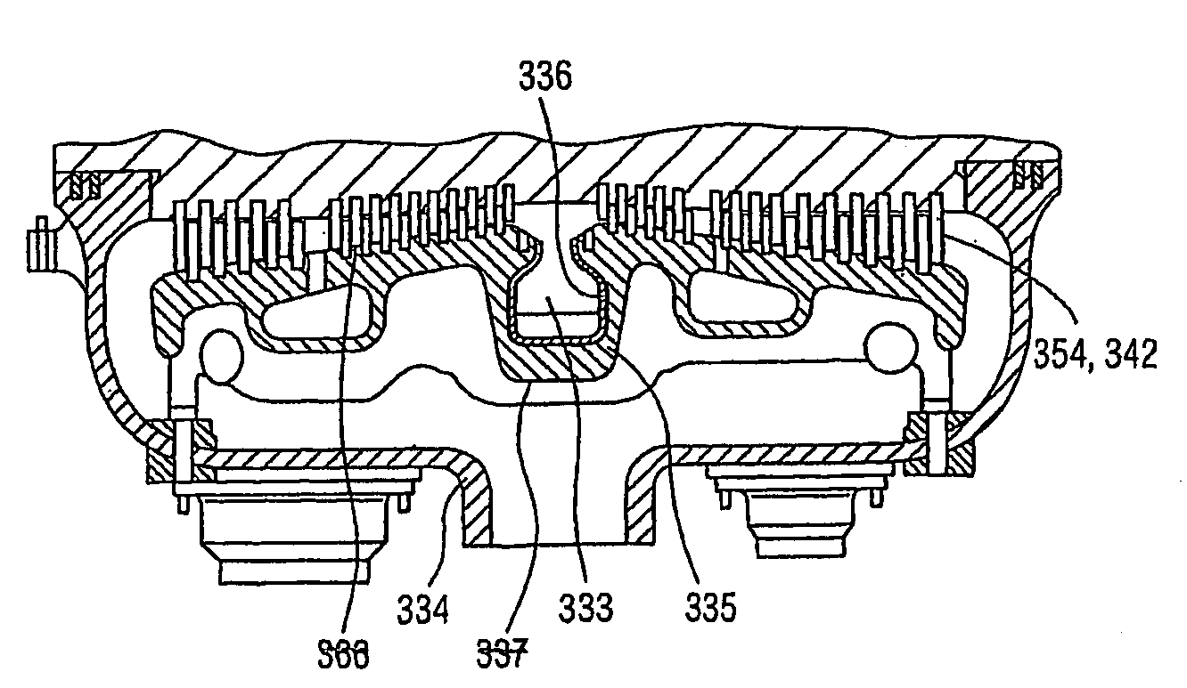
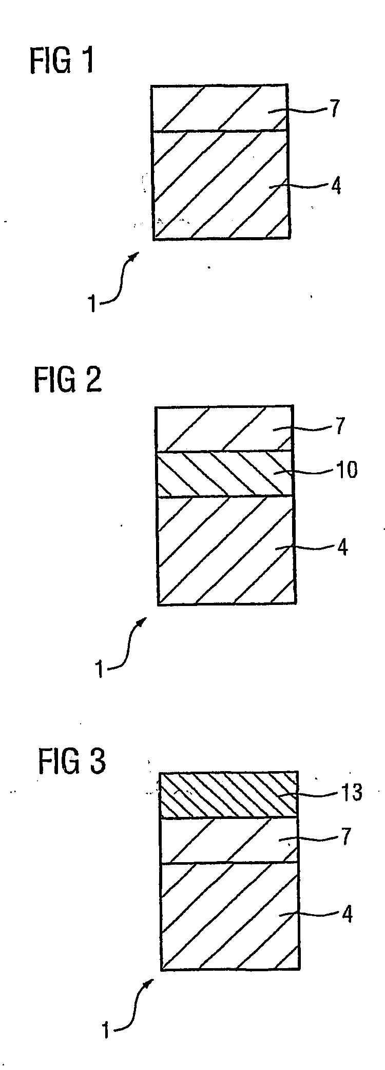
[0036]FIG. 1 shows a first exemplary embodiment of a component 1 for the use according to the invention. The component 1 is a component or housing, in particular a housing 335 of an inflow region 333 of a turbine (gas, steam), in particular of a steam turbine 300, 303 (FIG. 8), and comprises a substrate 4 (e.g. bearing structure) and a thermal barrier coating 7 applied to it.

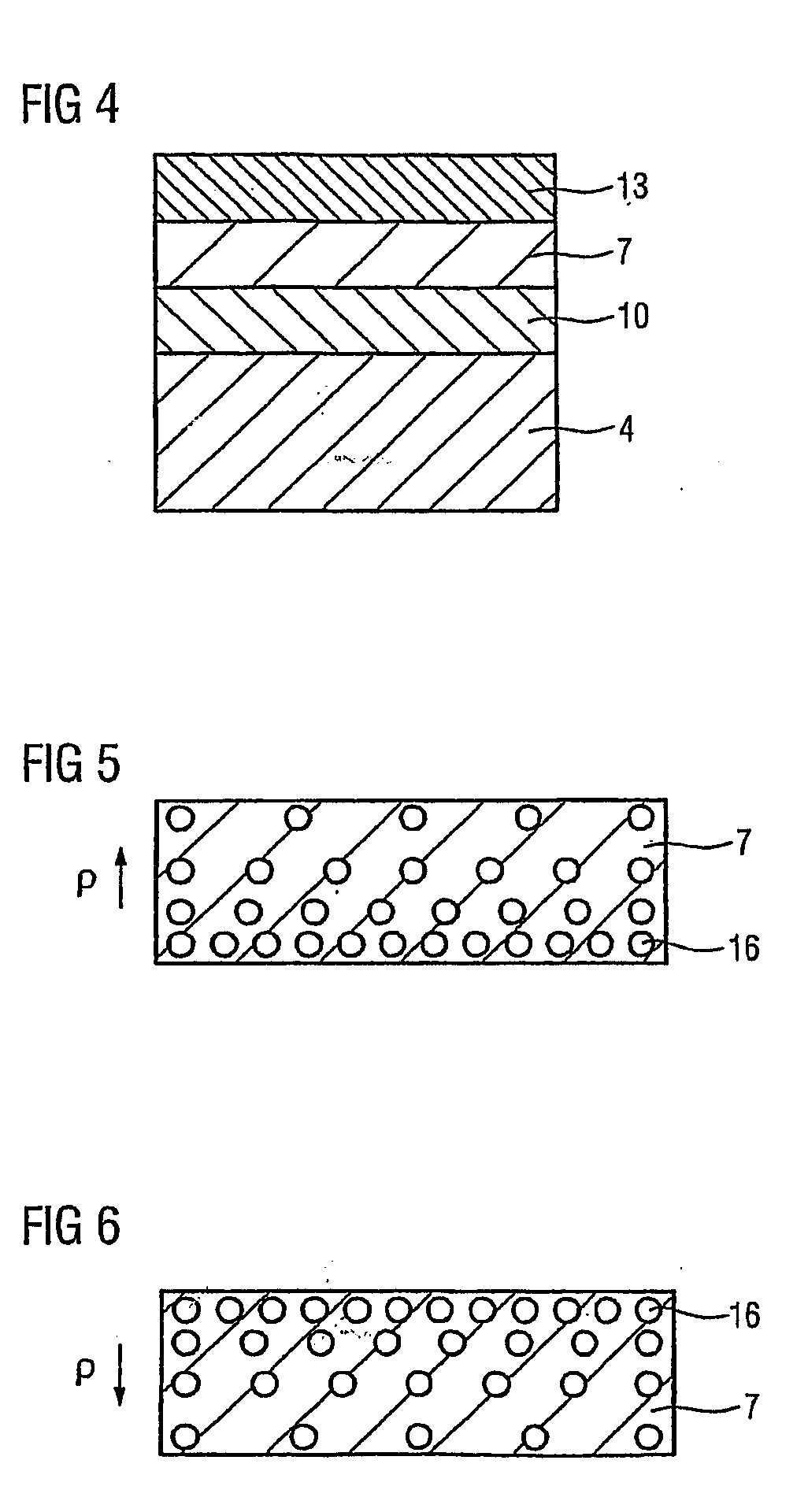
[0037]The thermal barrier coating 7 is in particular a ceramic layer which consists, for example, of zirconium oxide (partially stabilized, fully stabilized by yttrium oxide and / or magnesium oxide) and / or of titanium oxide, and is, for example, thicker than 0.1 mm. It is in this way possible to use thermal barrier coatings 7 which consist 100% of either zirconium oxide or titanium oxide. The ceramic layer can be applied by means of known coating processes, such as atmospheric plasma spraying (APS), vacuum plasma spraying (VPS), low-pressure plasma spraying (LPPS), as well as by chemical or physical coating metho...


PUM

PropertyMeasurementUnit
temperatureaaaaaaaaaa

Abstract

The invention relates to the use of a thermal insulating layer for a housing of a steam turbine in order to even out the deformation behaviour of different components based on different heatings of the components.

Description

CROSS REFERENCE TO RELATED APPLICATIONS[0001]This application is the US National Stage of International Application No. PCT / EP2004 / 013651, filed Dec. 1, 2004 and claims the benefit thereof. The International Application claims the benefits of European Patent application No. 03028575.3 filed Dec. 11, 2003. All of the applications are incorporated by reference herein in their entirety.FIELD OF THE INVENTION[0002]The invention relates to the use of a thermal barrier coating and to a steam turbine.BACKGROUND OF THE INVENTION[0003]Thermal barrier coatings which are applied to components are known from the field of gas turbines, as described for example in EP 1 029 115 or WO 00 / 25005.[0004]It is known from DE 195 35 227 A1 to provide a thermal barrier coating in a steam turbine in order to allow the use of materials which have worse mechanical properties but are less expensive for the substrate to which the thermal barrier coating is applied. The thermal barrier coating is applied in the ...

Claims


Application Information

Patent Timeline
Patent Type & Authority Applications(United States)
IPC IPC(8): F01D25/08C23C28/00C23C30/00F01D5/28F01D9/04F01D11/18F01D25/00F01D25/14
CPCC23C28/347C23C28/36C23C30/00F01D5/288F01D9/047F01D25/007C23C28/341C23C28/3215C23C28/3455F05D2220/31C23C28/321C23C28/345F05D2230/90F01D25/145F01D25/14F01D11/18F01D5/28
Inventor SCHMITZ, FRIEDHELMWIEGHARDT, KAI
Owner SIEMENS AG
Learn More