Linear Compressor

a compressor and linear technology, applied in the direction of motor/generator/converter stopper, dynamo-electric converter control, pump parameter, etc., can solve the problems of increasing the pressure and temperature of refrigerants in the restricted space, reducing the efficiency of linear compressor, and low efficiency, so as to achieve efficient variation of compression capacity

Inactive Publication Date: 2009-09-17
LG ELECTRONICS INC
View PDF3 Cites 17 Cited by
  • Summary
  • Abstract
  • Description
  • Claims
  • Application Information

AI Technical Summary

Benefits of technology

[0028]The present invention is achieved to solve the above problems. An object of the present invention is to provide a linear compressor which can efficiently vary a compression capacity according to load, by controlling an operation frequency of a linear motor and a stroke of a piston, even if a natural frequency of the piston is varied by the load.
[0032]Preferably, even though the stroke is varied by the load, the linear motor maintains efficiency of the linear compressor and a compression force of the refrigerants, by linearly reciprocating the movable member to reach a top dead center.
[0036]Accordingly, when the linear motor applies the current to the coil wound body, the electromagnetic force is always generated at the point of the coil wound body adjacent to the top dead center, and the permanent magnet is linearly reciprocated by the interactions with the electromagnetic force of the coil wound body, so that the piston can reach the top dead center to improve efficiency of the linear compressor and the compression force of the refrigerants.

Problems solved by technology

However, the more the actual load increases, the more the pressure and temperature of the refrigerants in the restricted space increase.
However, the natural frequency fn of the piston gets smaller than the operation frequency fc of the linear motor in a low load area, and thus the piston is transferred over the TDC, to apply an excessive compression force.
The linear motor is not operated in the resonance state, thereby decreasing efficiency of the linear compressor.
Therefore, the linear motor is not operated in the resonance state, which results in low efficiency.
Furthermore, the linear compressor cannot actively handle and rapidly overcome the load.
Accordingly, the piston 6 cannot reach the TDC, which results in low efficiency and compression force of the linear compressor.

Method used


Image

  • Linear Compressor
  • Linear Compressor
  • Linear Compressor

Examples


Embodiment Construction

[0050]A linear compressor in accordance with preferred embodiments of the present invention will now be described in detail with reference to the accompanying drawings.

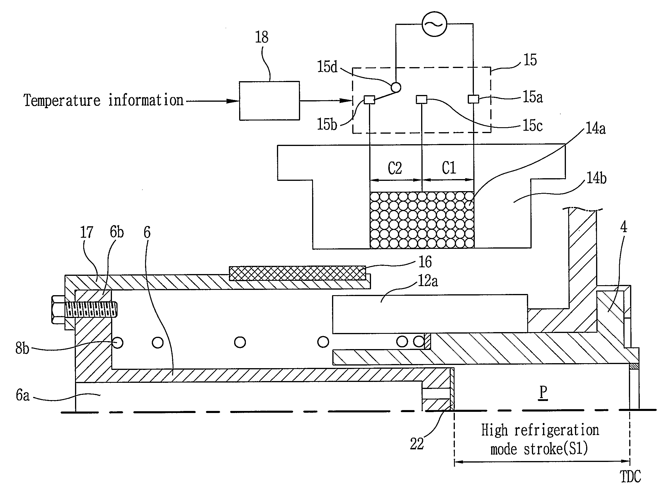
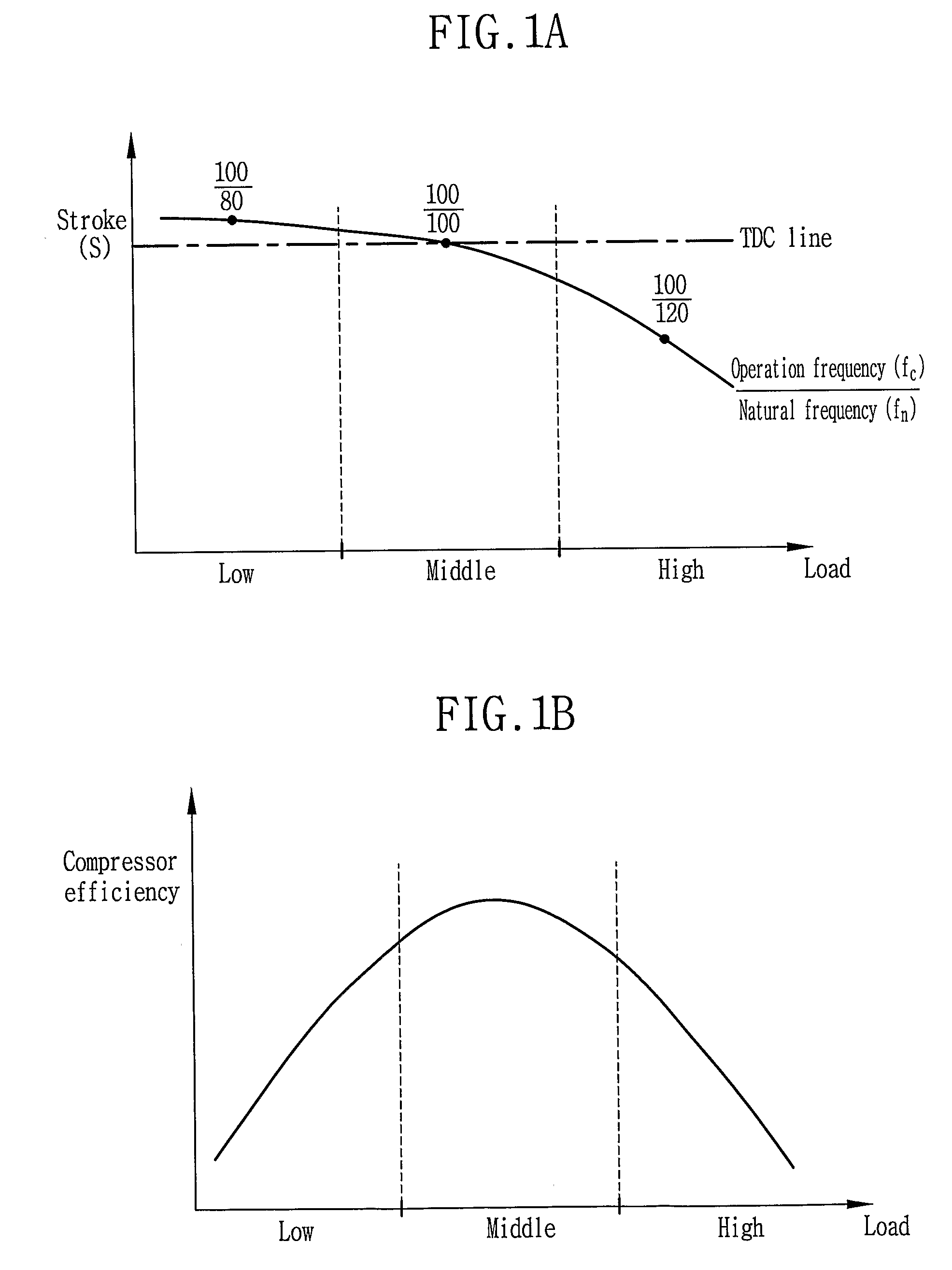
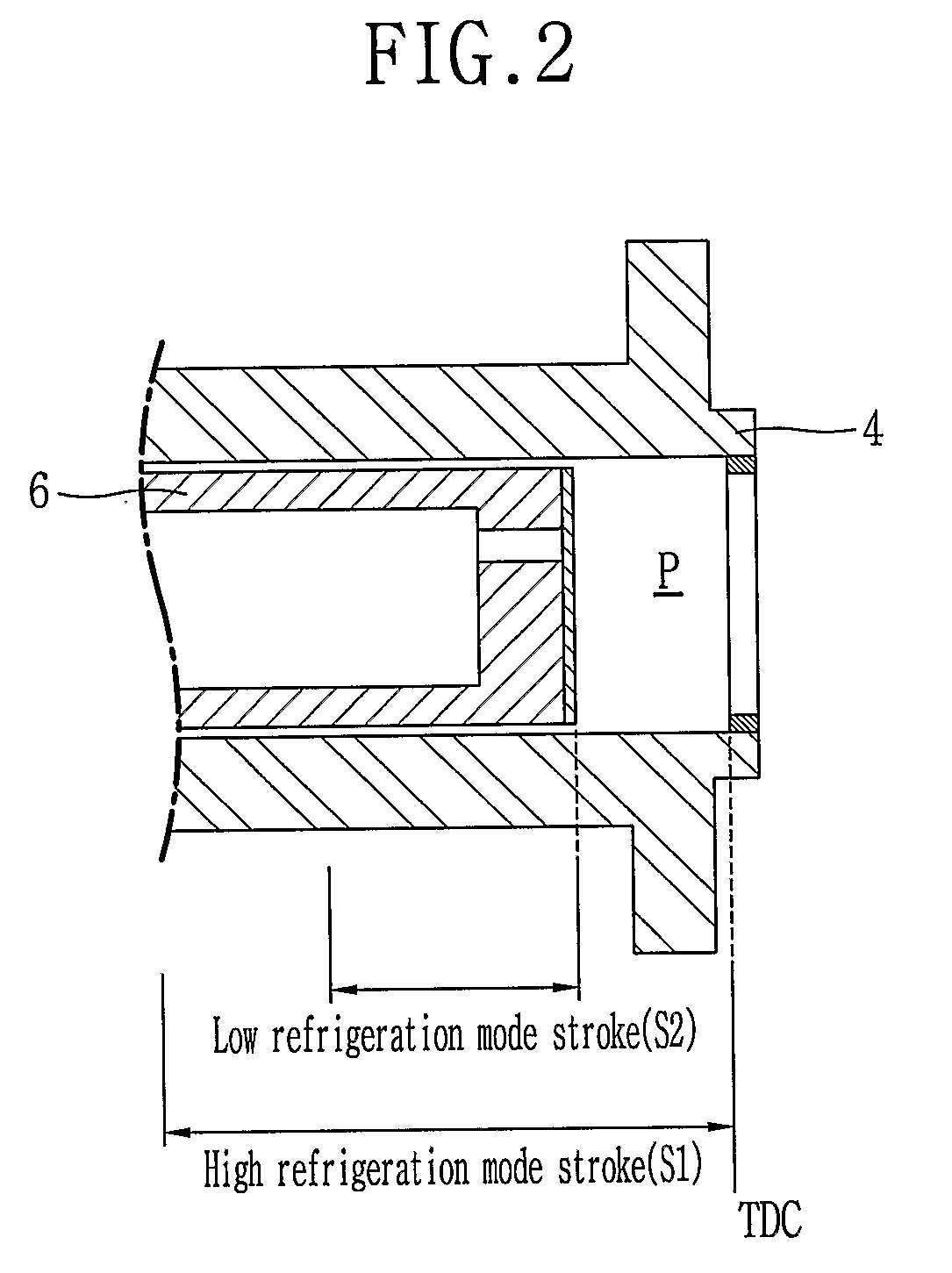
[0051]As shown in FIG. 3, in the linear compressor, an inlet tube 2a and an outlet tube 2b through which refrigerants are sucked and discharged are installed at one side of a closed vessel 2, a cylinder 4 is fixedly installed inside the closed vessel 2, a piston 6 is installed inside the cylinder 4 to be linearly reciprocated to compress the refrigerants sucked into a compression space P in the cylinder 4, and various springs are installed to be elastically supported in the motion direction of the piston 6. Here, the piston 6 is connected to a linear motor 10 for generating a linear reciprocation driving force. As depicted in FIGS. 4A and 4B, even if a natural frequency fn of the piston 6 is varied by load, the linear motor 10 controls its operation frequency fc to be synchronized with the natural frequency fn of the ...


PUM


Abstract

The present invention discloses a linear compressor in which a piston is driven by a linear motor and linearly reciprocated inside a cylinder to suck, compress and discharge refrigerants. Even though load is varied, the linear compressor performs the operation in a resonance state by estimating a natural frequency of the piston and synchronizing an operation frequency of the linear motor with the natural frequency of the piston, and efficiently handles the load by varying a compression capacity by changing a stroke of the piston.

Description

TECHNICAL FIELD[0001]The present invention relates to a linear compressor which can rapidly overcome load and improve compression efficiency, by synchronizing an operation frequency of a linear motor with a natural frequency of a movable member varied by the load, and varying a stroke of the movable member according to the load.BACKGROUND ART[0002]In general, a compressor that is a mechanical apparatus for increasing a pressure, by receiving power from a power unit system such as an electric motor or turbine and compressing air, refrigerants or other various operation gases has been widely used for home appliances such as a refrigerator and an air conditioner or in the whole industrial fields.[0003]The compressors are roughly divided into a reciprocating compressor having a compression space through which operation gases are sucked or discharged between a piston and a cylinder, so that the piston can be linearly reciprocated inside the cylinder to compress refrigerants, a rotary com...

Claims


Application Information

Patent Timeline
Patent Type & Authority Applications(United States)
IPC IPC(8): F04B49/00F04B35/04H02K33/02H02P31/00
CPCF04B35/045H02K33/16F04B2203/0404F04B2201/0206
Inventor CHOI, BONG-JUNKIM, HYUNSHIN, JONG-MINJANG, CHANG-YONGPARK, SHIN-HYUNJEON, YOUNG-HOANROH, CHUL-GI
Owner LG ELECTRONICS INC
Why Eureka
Try Eureka